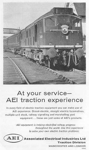
BR/Sulzer Type 2 D5130 features in a 1962 advertisement for AEI Traction Division. The Type 2s did not have the honour of hauling many named trains, but 'The Orcadian' was very much their province, being introduced in 1962 as a fast four hour service to Wick/Thurso, departing Inverness at 9.05am.
In 1928 Associated Electrical Industries (AEI) was established as a result of the merger of rivals Metropolitan-Vickers (MV) and British Thomson-Houston (BTH). This combination would be one of the few companies with the ability to compete with Marconi's Wireless Telegraph Company or the English Electric Company. Also included in the new group were Edison Swan Electric Company (Ediswan) and Ferguson Pailin of Openshaw, Manchester (which BTH had been in the process of buying in 1928). MV & BTH remained separately quoted companies, were frequently in competition with each other, with poor communication across the companies and intense rivalry, which amongst other things prevented AEI from gaining effective control.
By 1956 the main companies in the AEI Group were: BTH, Metropolitan-Vickers Electrical Co, Edison Swan Electric Co, Ferguson Pailin, AEI Lamp and Lighting Co, Hotpoint Electric Appliance Co, Coldrator, Newton Victor, Premier Electric Heaters, Siemens Brothers and Co, Sunvic Controls & AEI-Birlec.
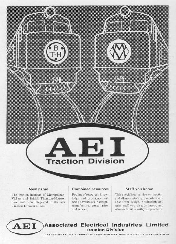
During 1957 & 1958 reorganisation commenced to assimilate the three subsidiary companies into one, with all to use the AEI brand name, whilst separate trading of the constituent companies would cease. On January 1st 1960 AEI stopped using the names BTH and Metrovick. The three main manufacturing companies were reorganised into divisions of AEI: Turbine-Generator, Transformer, Traction, Switchgear, Instrumentation, Electronic Apparatus, Heavy Electrical Plant, Motor and Control Gear, Cables, Construction (Cables and Lines) Radio and Electronic Components & Telecommunications. What was planned on paper suffered badly in reality, sales fell in the heavy electrical industry because the brand name 'AEI' was unknown, leading to a serious drop in AEI's stock price. The two separate management structures were never successfully combined, by the mid-1960s the entire AEI empire was in financial trouble.
In 1959 AEI came to an arrangement with Alco, who built both diesel engines and the mechanical parts of locomotives, and was an established manufacturer with a worldwide market base. Added to that was the established access to GE technology on the BTH side of AEI, which meant that AEI could supply equipment that was interchangeable with that which GE supplied to Alco.
By 1961 AEI was Britain's largest electrical manufacturer which included design, manufacture and distribution; the company had 103,450 employees with Works in more than fifty UK towns.
Perhaps the greatest opportunity for AEI with regard to a large locomotive order came in 1961 with the consortium of BRCW/Sulzer/AEI producing a six axle 2,750hp 114 ton (gross) demonstrator as the next step in British Railways Type 4 development. As dealt with elsewhere in this website this proved to be a dead end for BRCW & AEI.
Throughout the life of AEI the company struggled with the internal rivalries between BTH & MV, though the subsidiaries themselves were very successful especially in the War years (1939 - 1945), the parent never resolved the serious problem of integration. The drastic revitalisation and leadership required to enact this major change was not forthcoming and the whole issue faded into oblivion when GEC made a GBP120 million bid for AEI, with the merger taking effect on Thursday, November 9th, 1967.
Interestingly less than a year later on September 6th, 1968, GEC also acquired The English Electric Company, at a stroke, literally, a multitude of competing electrical suppliers at the onset of British Railways Modernisation Plan were now consolidated into one major company.
Rolling stock on British Railways that utilized AEI electrical equipment (this list is not exhaustive):
Ruston & Hornsby 0-6-0 shunter, Class 07: 2985 - 2998, one traction motor.
BR/Sulzer Type 2s, Class 25: 5176-5299, 7500-7677 (25026-25327), four AEI 253 AY traction motors.
BRCW/Sulzer/AEI Type 4, D0260 'Lion', (introduced 1962), six AEI traction motors.
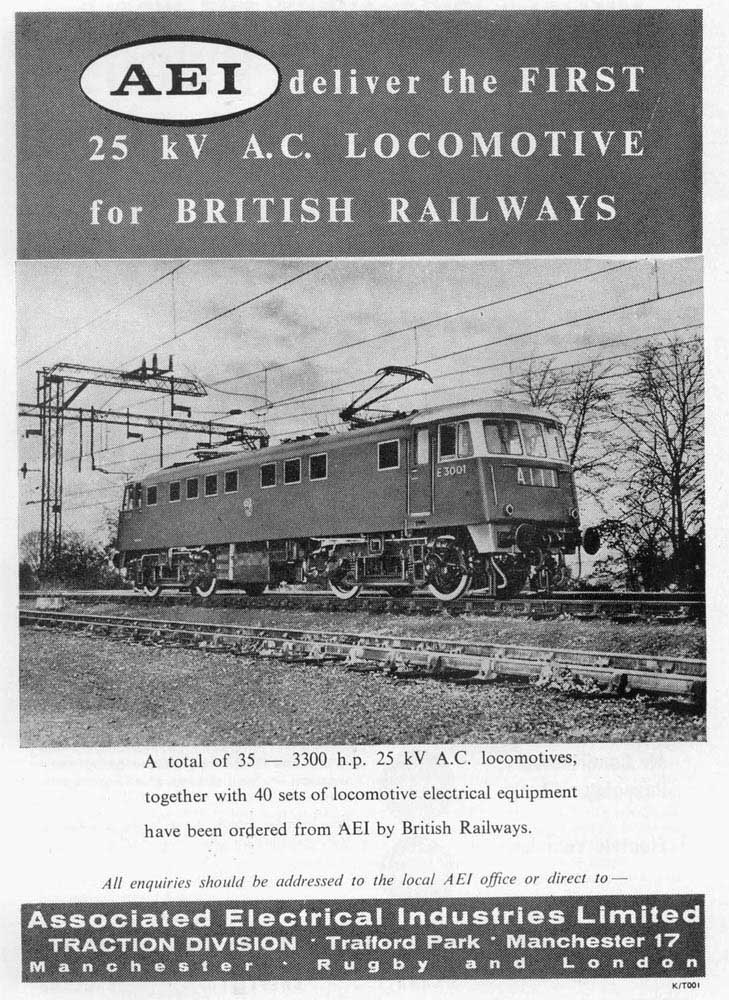
AEI/BTH BoBo Type A Electric, Class 81: E3001-E3023, E3096/97 (81001-81023), four type 189 847 hp d.c. traction motors.
AEI/MV BoBo Type A Electric, Class 82: E3046-E3055 (82001-82008), four type 189 847 hp d.c. traction motors.
BR/AEI BoBo Type A Electric, Class 85: E3056-E3095 (85001-85040), four type 189 847 hp d.c. traction motors.
Class 304 four car emu LMR 001-045, four AEI 207hp dc traction motors, introduced 1960.
Class 303 four car emu ScR 001-091, four AEI 207hp dc traction motors, introduced 1960.
Class 311 four car emu ScR 092-110, four AEI 222hp dc traction motors, introduced 1967. Possibly the last powered rolling stock on BR to have electrical equipment using the AEI brand.
Addendum No.1
Response from Steve Palmano with regard to the AEI 253 traction motors.
As I understand it, the problems with the AEI 253 motors on the BR Class 25 class were not by and large intrinsic to the motor itself, but the result of incorrectly set control systems, particularly in respect of field diversion. The effects were worse when two locomotives with widely different settings were operating in MU. The use of road-speed controlled field diversion on late class 25 production was an improvement. I think this had been part of the GE lexicon for some time. AEI may have taken a while to get to grips with the different nature of the 253 as compared with its traditional motors.
Brian Webb summed up the situation thus: “The outcome was that it was considered to be variations in equipment, notably the field divert relays, and their poor adjustment which caused this problem. Other factors included variations in traction motor cooling due to blowers being faulty or incorrectly maintained, diesel engines putting out to high bhp due to governor changing, load regulator switches failing in closed position and causing current fluctuations, and excessive motor current.”
That is not to say that operation of the AEI 253 motor in continuous high-speed service would not have thrown up problems, but it is difficult to imagine that these could not have been solved. The prototype GE 761 motor was subject to ongoing improvements over the years, and was eventually capable of handling around 700 hp. All of this was presumably transferable to the AEI 253. Of course, in an environment where maintenance was indifferent or even poor, which does seem to have been the case for BR, then any kind of reasonably advanced technology was at risk. Perhaps the AEI 165 motor, counterpart to the GE 752 standard gauge unit, would have been less susceptible to problems, but then the track would have suffered more from its higher unsprung mass in an axle-hung installation.
Thus I’d say that AEI had made a forward-looking decision in choosing the 253 motor for the Lion. It anticipated that in the lifetime of such a locomotive, track speeds would need to rise, perhaps up to something like 110 mile/h for locomotives with axle-hung motors, and therefore that reducing unsprung mass was highly desirable, if not essential. That was a vector that might have forced the further development of lightweight motor design with concomitant traversing of a learning curve, but that would have led to a better result than falling back upon the “safe” option of a heavyweight motor.
Of course, BR had made the quest for higher power and speed with a 19-ton axle loading unnecessarily difficult by its insistence upon the very heavy Sulzer 12LDA28 engine, which turned out to be a real problem child, and an expensive one as well. Tufnell gave the price of the Sulzer engine as Ł45k as compared with Ł26k for the English Electric 16CSVT; this would have been in the early 1960s. Weights were given as 22.3 tons for the 12LDA28 and 19.4 tons for the 16CSVT. The heavy engine meant that all other parts of the locomotive had to be as light as possible, in some cases more so than good engineering judgement might have otherwise indicated. The Lion came in at the specified maximum of 114 tons. The first batch of class 47s were overweight at 117 tons, but it appears that if Brush had been admonished for that transgression, it got off by promising to do better in the future. Deletion of the electric train heating facility, a majorly retrograde move, seems to have been part of “doing better”.
![]()
The US based American Electric Company sold their products to the English market through the The Laing, Wharton & Down Company, the latter formed in 1886 and incorporating in 1889. The American Electric Company was later renamed the Thomson-Houston Company and in 1892 became the General Electric Company (USA) following the merger of the Thomson-Houston Company and Edison General Electric. Two years later in 1894 the Laing, Wharton and Down Construction Syndicate was renamed British Thomson-Houston (BTH) having acquired the British rights to the Thomson-Houston patents, with BTH being majority owned by General Electric Company (USA). Over time BTH became well known for steam turbines and electrical systems.
The Power Act of 1900, which would bring electricity supplies to large areas of the country included BTH as one of the suppliers. Rugby was selected as a production center, aided by nearby coal supplies and good railway connections, land was purchased in 1900 with manufacturing commencing in March 1902, principally steam turbines, motors, converters & switchgear.
The advancement of electrified underground and commuter railway routes in the United Kingdom saw BTH win contracts in 1903 from the North Eastern Railway to provide electrical equipment for motor units, carriages and laying of third rail and the District Line's use of the Sprague-Thomson-Houston system of multiple unit train control. In 1904 BTH became the contractors for the Central London and Great Northern and City lines electrification using direct current.
1909 saw BTH provide electrical equipment for London's first trolley buses. Equally important was the production of lightbulbs, made possible by the growth of the electricity grid. Expansion because of World War One and afterwards saw factories established at Birmingham, Chesterfield, Coventry, Lutterworth & Willesden, with production now featuring domestic appliances.
The diversity of BTH was illustrated in 1922 when it became one of six telecommunications companies to found the British Broadcasting Company (BBC).
The various BTH works specialised in items produced: Rugby - turbo plant, heavy machinery, electric traction equipment and lighting and radio material; Birmingham - electric motors; Coventry - radio apparatus and fractional horse-power motors and Willesden - switch gear.
A proposed merger of a number of electrical companies in 1926, headed by GEC of America, came to nothing. However in 1928 BTH merged with Metropolitan Vickers, also included were the companies Edison Swan Electric Company (Ediswan) and Ferguson Pailin of Openshaw, Manchester (which BTH had been in the process of buying). The merger included the acquisition of the Ordinairy shares in BTH held by General Electric of USA. In 1929 the merged entities became known as Associated Electrical Industries (AEI). Although MV & BTH were now under the same roof with very similar product lines they kept their identities & operations separate, which would eventually lead to serious commercial rivalry between them, causing a serious internal destabilising influence for AEI.
The Depression years hit the company hard, but AEI continued to expand its (BTH) Rugby plant. During 1935/1936 the Rugby plant was involved with Frank Whittle in constructing one of the world's first jet engines. BTH appeared disinterested in the development of the jet engine, in 1943 Rolls Royce took over the production.
In 1950 the LMS/Ivatt originated branch line prototype diesel electic locomotive 10800 was built using the consortium of NBL/Paxman/BTH. Surprisingly NBL had already established a relationship with GEC to supply NBL-GEC diesel-electric and electric locomotives.
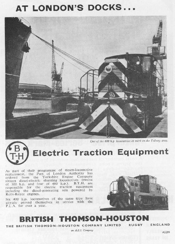
During 1950 BTH received two export orders. One was from NSWGR for ten of its twin-engined 41 class, and the other from WAGR for 18 of its Y class. Both were shunting/transfer locomotives, but suitable for some line service. Both used Paxman high-speed engines. For the NSWGR 41, BTH worked with Metro-Cammell as mechanical parts supplier, whereas for the WAGR Y, it worked with Clayton. The 41 was close to being a failure, inadequate design leading to serious problems with engine cooling. The Y fared a bit better, though later events revealed serious inadequacies with the Clayton company.
The BTH/Paxman combination reappeared in a British Railways Modernisation Plan order, the 82xx series (later Class 15), with Clayton handling the mechanical parts. This was somewhat successful as a second order was recieved. However of far greater impact for BTH was its selection as the electrical equipment supplier for the BR-built, Sulzer-engined 5xxx series (later Class 24/25) from the Modernisation Plan, a production run which produced 176 locomotives. A further 302 would be built, but using AEI branded equipment. Thus BTH was now involved with true line-service locomotives.
The successes for other parts of BTH organisation continued into the 1950s, with BTH constructing Europe's largest turbine works, at Larne in 1957.
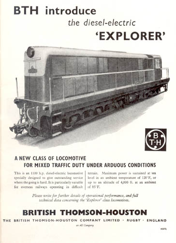
Looking at the export market in the late 1950s BTH, with Clayton and Lister-Blackstone commissioned the Explorer CM-gauge prototype, which was ready in 1959. This featured a Lister-Blackstone engine, BTH electrical equipment and mechanical parts by established partner Clayton. Possibly Lister-Blackstone saw this as a pathway into the mainline locomotive market, as the cost was shared between itself and BTH.
At 1100 hp (gross), with Co-Co running gear and weighing 72 long tons, the Explorer may be compared with standard road switchers from the major worldwide builders. Previous engine partner Paxman offered high-speed engines which were in a lower power range than needed for the Explorer. The Alco DL531 was slightly lighter (in CM-gauge form) and marginally less powerful, at 975 hp (gross). The GE U9C was somewhat heavier and had a nominal power of 990 hp (gross), but this was a high-altitude, high-ambient temperature rating, and the UIC number was 1060 hp. The Alco & GE utilised 6-cylinder in-line engines, whereas the Lister-Blackstone featured the relatively complex 12-cylinder double-bank form, albeit still medium-speed. This complexity allied to its weight put it at an immediate major disadvantage. There were no production orders from this prototype.
In 1959 EMD did not yet have a six-motor model in this power class. English Electric no doubt could have offered a Co-Co version of its existing eight-cylinder Latin American model with either the 8SRKT or 8SVT engine, by 1959 delivering 1100 hp. And more power would have been available from the 8CSRKT or 8CSVT engine with but minor weight penalty. Within two years Alco offered the DL535, delivering 1350 hp (gross), still with six cylinders, and weighing around 72 long tons in CM-gauge form.
The Explorer was built by the Clayton Company of Hatton, Derbyshire, order number 3548 of January 1959, it was powered by a Lister Blackstone ERS.12T 12 cylinder twin-bank engine powering BTH electrics. Cylinders were 8.75 x 11.5 inches, maximum crankshaft speed was 800rpm, output speed through the phasing gears was 1,320rpm providing 1,100hp. Either crankshaft could be uncoupled in an emergency.
The locomotive weighed 72tons and rode on metre gauge Co-Co bogies of rubber cone pivot Alsthom style. Alsthom (originally ALS-Thom(son)) had a similar relationship with GE as did BTH, and it appeared that design ideas also travelled 'horizontally' between GE 'associates'. This aspect of the Explorer design was carried over to the later AEI Zambesi type.
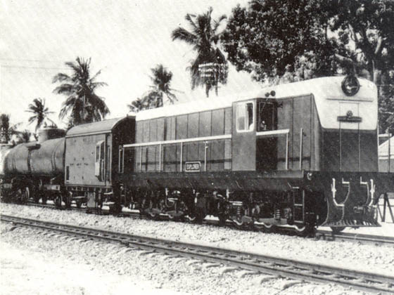
It was leased to the East African Railways who later bought it outright. In the late 1960s EAR reclassification it was assigned Class 79. It was allotted to the Kenya Railways in 1977, though by October of that year it was recorded as 'stabled for scrap' on the roster. As of 2005 the 'Explorer' locomotive still existed, very much intact and still bearing its number and nameplates. It was earmarked for the Nairobi Railway Museum when funding become available. The locomotive was retired to the sidings of the Training Centre in Nairobi with an expectation that it would be transferred to museum stock. Unfortunately, as late as May 2011, it was purchased from Kenya Railways and scrapped in situ.
A late 1950s BTH contract was with NZR for 18 Dsc class shunting and light line-service locomotives. Rolls Royce was the engine supplier. Clayton built the mechanical parts, and apparently made a very poor job of what was basically a good design. NZR was not impressed by Clayton’s lack of capability, and when it wanted more of the same locomotives, it built them itself.
AEI's internal reorganisations and the continuing rivalry between BTH and Metropolitan Vickers presented management with a considerable challenge. One aspect of unification was to promote the AEI brand name in place of the BTH & MV names, a move which backfired on AEI because the brand name of AEI was unknown, leading to falling sales, further impacting profitability. The BTH brand name was discontinued effective January 1st 1960 - see AEI above.
Continued attempts to bring together the two divisions together did not meet with the greatest of success, however all would be of no consequence when GEC successfully bid for AEI in 1967. At the time the 'AEI' brands included Metropolitan-Vickers, BTH, Edison Swan and Ediswan, Siemens Brothers, Hotpoint, Birlec and W. T. Henley. With this acquisition GEC became the United Kingdom's largest electrical group.
During the 1980s the facilities at Rugby were downsized with many building being torn down and the land reused for new development.
Rolling stock on British Railways that utilized BTH electrical equipment (this list is not exhaustive):
BTH/MV/WH Allen 3 diesel electric shunters (introduced 1931) for Ford Motor Company, Dagenham, four BTH 26hp traction motors.
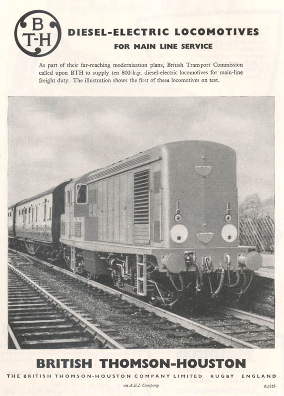
BR/NBL/Paxman Bo-Bo 10800 (introduced 1950), four BTH traction motors.
BR 0-6-0 shunter, 'Class 08': 3152-3166 (all withdrawn by late 1967), two BTH traction motors.
BR/Sulzer Type 2 Class 24/25: 5000 - 5175 (24001-24150, 25001-25025), four BTH 213hp traction motors.
BTH/Paxman Type 1 Bo-Bo: 8200 - 8243 (introduced 1957), four BTH traction motors.
Ruston & Hornsby 0-6-0 shunter: PWM650 - PWM654, one BTH traction motor.
Brush BoBo electric ES1 class (introduced 1902): 26500 & 26501, four BTH traction motors.
Battery Electric LMS shunter (introduced 1917): Bel 2, two BTH traction motors.
LMR Wirral/Mersey emu Class 503 (introduced 1956): M28371M-M28394M, four BTH 135hp traction motors.
LMR Wirral/Mersey emu Class 503 (introduced 1938): M28672M-M28690M, four BTH 135hp traction motors.
SR 6-PUL emu: 3001-3020, 3041-3043: eight BTH 225hp traction motors.
SR 5-BEL emu: 3051-3053, four BTH 225hp traction motors.
![]()
Metropolitan-Vickers Electrical Company (MV) grew out of the American owned firm of British Westinghouse. The company was formed in 1899 and was located at Trafford Park, Manchester, being well known for their industrial electrical equipment & generators, steam turbines and diesel locomotives. During World War One it was felt that American ownership of the company had been a hindrance to gaining government contracts, a British holding company was established in 1916 to acquire the American shares, with finance provided through the Metropolitan Carriage, Wagon & Finance Company and Vickers. By 1918 British Westinghouse Electrical & Manufacturing was finally under British control, continuing under the same name until requested by American Westinghouse to discontinue the use of 'Westinghouse' in the company name. The acquisition by Vickers in 1919 of Metropolitan Carriage, Wagon & Finance Company included 99% of the share capital, changing the name to the short-lived Vickers Electrical Company Ltd and then to the more familiar Metropolitan-Vickers Electrical Company (MV) in September 1919.
The diversity of MV was illustrated in 1922 when it became one of six telecommunications companies to found the British Broadcasting Company (BBC).
During 1926 a new company, Metropolitan-Vickers-GRS Limited, was formed jointly with the General Railway Signal Company of Rochester, New York, to sell railway signalling equipment, under the design of the American company, but made at the Trafford Park works.
Many problems faced British industry in the 1920s; low investment, political & labour unrest, import & export restrictions, all factors with many others culminating in the General Strike in 1926. Despite these ongoing issues MV expanded their markets both at home and overseas. The Electricity Supply Act of 1926 and the formation of the electricity 'grid' produced many orders for heavy plant - turbines, generators, switchgear and industrial motors.
Vickers had anticipated amalgamations within the electrical manufacturing industry, these had not materialised, thus when a cash offer was received in 1928 by the International General Electric Company to purchase a controlling interest in the company, Vickers took the offer. However they did retain a considerable number of Ordinairy shares.
Overseas a number of offices were opened, with major successes in South Africa, Australia & New Zealand. Most unusual was its prosperous relationship established with the Bolshevik regime in Russia for the Moscow Metro development.
In 1928 MV merged with British Thomson-Houston (BTH) and on January 4th 1929 both came under the umbrella of Associated Electrical Industries (AEI). Agreement was also reached with International General Electric Co (USA) to acquire that company's shareholding in BTH. Although MV & BTH were now under the same roof with very similar product lines they kept their identities & operations separate, which would eventually lead to serious commercial rivalry between them, causing a serious internal destabilising influence for AEI.
MV survived the depression years of the early 1930s with help from overseas contracts, a major achievement in Brazil was the awarding of a contract for railway electrification, whilst a scandal in Russia led to the arrest & conviction of six of their engineers for alleged sabotage & espionage. The Russian authorities claimed that the British engineers had gained considerable knowledge about Moscow's physical layout whilst working on the Moscow Metro project. The British Government obtained the release of the engineers and resumption of trade after a short embargo.
The Second World War brought huge demands upon MV production of a wide variety of items for all the Armed Services. This included 43 (?) Avro Manchesters (the first 13 being destroyed in a Luftwaffe bombing raid on Trafford Park) and 1,080 Avro Lancasters built at facilities at Manchester Ringway and Avro's Woodford plant.
Post war production boomed, but so did the rivalry between MV & BTH, the latter opening a huge turbine works at Larne, countered by MV establishing a smaller transformer factory at Wythenshawe. As the 1950s progressed MV made a profitable name for itself in domestic appliances - refrigerators, cookers etc.
In 1949 MV formed a joint venture with Beyer, Peacock & Co, known as Metropolitan-Vickers-Beyer-Peacock to design, manufacture and assemble non-steam powered railway locomotives. A new factory was established at Bowesfield, Stockton-on-Tees.
MV worked with Sulzer on two orders, during 1950/51 they supplied equipment for the two CIE prototypes (1100/1101) and in 1956 for the CIE B class, with BRCW being the primary contractor.
In its railway applications MV appeared somewhat backward looking. The 1.5kV DC 46 Class electric locomotives supplied to NSWGR and ordered just ahead of the WAGR X class was a new design but conformed to the obsolescent 1930s articulated bogie form with a Co+Co wheel arrangement. Using more current thinking English Electric had been building large DC electric locomotives with independent swing-bolster Co-Co bogies since the late 1940s.
In 1950 MV received an order from WAGR for 48 of the X class. This was a much larger order than other British makers were getting at the time. MV worked with Crossley as engine supplier and used the joint venture with Beyer-Peacock for the mechanical parts and assembly. Although Beyer-Peacock was a competent builder, it was somewhat backward-looking in the design department, however the use of Crossley as the engine supplier proved to be less than perfect. The X class locomotive used an obsolete rigid-frame 2-Do-2 wheel arrangement, and would not have helped the way MV was perceived by potential buyers. Possibly WAGR and/or Beyer Peacock saw the X class as being essentially the diesel counterpart to its W-class 4-8-2 steam locomotives then being built by Beyer Peacock.
Then in 1954 MV took a 94-locomotive order from CIE, for 60 A class and 34 C class. In numerical terms it appeared to be doing very well. This CIE order was placed before the WAGR X class had accumulated any significant service hours, and most likely prior to the Crossley engines revealing the magnitude and intractability of their problems. For the CIE order MV did not return to Beyer-Peacock for the mechanical portion, but went with Metro-Cammell as mechanical parts supplier, a company with whom BTH had established a relationship and would feature in later MV and AEI locomotive contracts.
MV would work with the Beyer-Peacock joint venture in 1955 for the British Railways Pilot Plan order for twenty Co-Bo (later Class 28) locomotives. These were also powered by a Crossley engine, which would prove to be their Achilles heel and no doubt seriously hindered MV’s chance of success as a supplier of diesel-electric locomotives.
As part of the unsuccessful move to unify the company MV's name technically disappeared on January 1st 1960 - (see AEI above).
Rolling stock on British Railways that utilized Metropolitan Vickers electrical equipment (this list is not exhaustive):
LMR Liverpool/Southport emu Class ??? (introduced 19??): M28301 - M28310M, four MV 265hp traction motors.
Hawksworth (GWR) & MV Co-Co 18100 (introduced 1951) gas turbine, six MV traction motors (later converted to 25kV AC No.E2001.
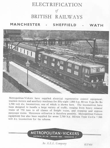
Gresley LNER/BR & MV Bo-Bo Class EM1 1500V DC electric loco E26000 - E26057 (introduced 1941/1950), four MV 467hp traction motors.
BR & MV Co-Co Class EM2 1500V DC electric loco E27000 - E27006 (introduced 1954), six MV 415hp traction motors.
MV/Crosley Type 2 Co-Bo 5700 - 5719 (introduced 1957) five MV traction motors.
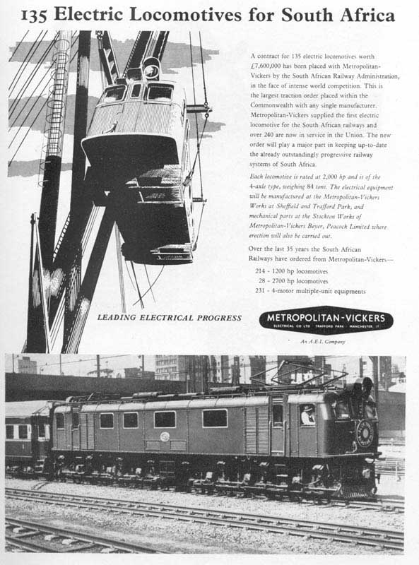 |
Advertisement circa 1957 showing MV's success in South Africa. The 1957 built Class 5E1 2280hp 84ton Bo-Bo mixed traffic locomotives feature in the advertisement's text but the photograph shows (I think) one of the 1944 built Class 3E 2,700hp 110ton Co-Co mixed traffic locomotives. |
Michael Wimmer has provided the following detail with regard to the above view:
....the advertisement of MV with regard to the 135 Locomotives sold to South African Railways is of particular personal interest. The picture in the ad is an 3E. My interest is more than passing because my father, William (Bill) Wimmer was the traction engineer for Met Vick in South Africa and he was responsible at the South African end for getting the order. I well remember the day the order was announced on the front page of the Johannesburg newspaper, along with the excitement in the family and the pride we felt in Dad. The chief design engineer at Trafford Park was Frank Whyman. In 1936/7 my parents lived in Manchester (Fallowfields) as my father had come over from South Africa in order to be familiarized with all the design and manufacturing processes. My father’s work was with the Chief Electrical Engineer of South African Railways (Wallace King) to do all the design specs for the arduous South African conditions.
The text in the ad does not refer to the 5E1, but correctly to the 3E. If my memory serves me correctly, this particular order was placed in 1953 for the 3E’s. When they were shipped to South Africa, they were unloaded in Durban, where my father had frequently to go to supervise the commissioning and testing of the locomotives. If these trips coincided with my school holidays, he would take me with him. His ‘in-laws’, my grandparents lived a short distance outside of Durban. We would ‘chase’ locomotives that were already in service to get pictures that could be sent back to Trafford Park in order to have them for publicity purposes. Met Vick’s South African Office was in Johannesburg, where, of course, I grew up. Naturally I recognize that the picture of the 3E is in Johannesburg station. It is entirely possible (if not almost certain!) that the picture was taken by my father.
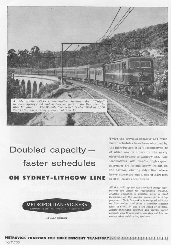 |
Advertisement circa 1957 for an order of electric locomotives for Australia. The locomotive featured is one of the forty 1950 built 3,820hp 108ton Co-Co electric locomotives built for the New South Wales Government Railways. | 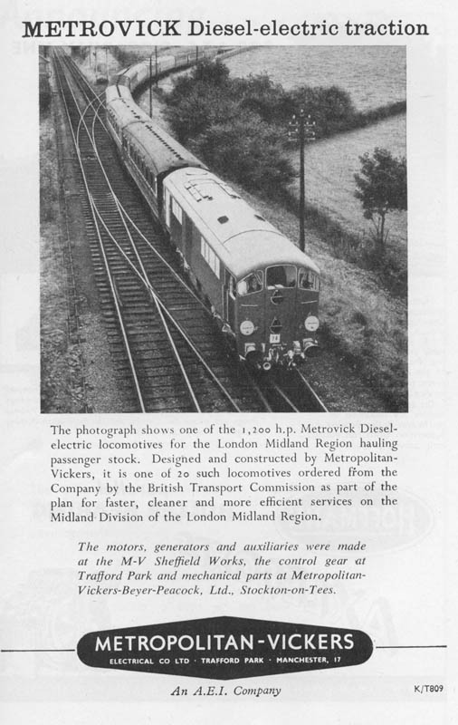 |
Advertisement showing one of British Railways Co-Bo diesel-electric locomotives under test. |
![]()
WDL Posting by Steve Palmano October 8th 2018.
In respect of the rivalry between BTH and M-V, and their pursuit of independent paths, perhaps symbolic was M-V’s formation of the joint venture with Beyer, Peacock in 1949 (M-V-BP) with the objective of supplying complete electric and diesel-electric locomotives, in which BTH played no part. The conventional approximation is that one third of the value of a diesel-electric locomotive resides in each of the engine, the electric transmission and the mechanical parts. So by having the joint venture build the mechanical parts and assemble the locomotives, M-V’s share of the total value was increased to half. In that case the initiative may have come from Beyer-Peacock, who had been rebuffed by English Electric when it made a similar proposal for a joint venture. Still, one could say that AEI top management was perhaps remiss in letting M-V go ahead without including BTH, and so improving the chances that the joint venture would reach “critical mass”. At the time the UK locomotive building industry was not short of capacity overall, although its distribution may not have been optimum. As a partner, B-P was known for good fit and finish, but it had no experience with modern traction, and was also known for clinging to some outmoded mechanical ideas.
The M-V-BP joint venture was wound up early in 1961, ostensibly for lack of orders and without anticipation that the situation would change. Apparently it had never been fully occupied. At the time M-V-BP had just built 100 out of 135 5E1 class electric locomotives ordered from M-V by South African Railways. The remaining 35 were built by Metro-Cammell (M-C). That looks as if it were a change of plan, as a 1960 May AEI brochure on the 5E1 class stated that all 135 were to be built by the M-V-BP joint venture. Perhaps AEI management pushed for or even engineered the closure of the joint venture, but nonetheless no doubt it was a welcome step in their plans to integrate BTH and M-V.
As previously said, M-V had placed the mechanical work associated with 94-locomotive CIE A- and C-class orders with M-C rather than with M-V-BP, even though the latter surely had the capacity to do it. In this case, M-V also itself undertook the final assembly work in premises rented for the purpose. Again one might have expected a more disciplined AEI top management to require that M-V use joint venture capacity unless there were cogent reasons to do otherwise. Possibly CIE had insisted that M-C be used, but that seems unlikely. Anyway, the last part of the SAR class 5E1 order seems to have established M-V’s relationship with M-C, who thereafter became AEI’s mechanical parts and assembly partner.
Another apparent anomaly was the CIE B class, in that they were built by BRCW, not by M-V-BP. These used spare Sulzer engines previously built for CIE’s abortive twin-engined 1800 hp proposal. M-V had been the electrical equipment supplier for CIE’s home-built, Sulzer-engined prototypes, although in that case it was effectively subcontracting to Sulzer, who had the contract for the whole powertrain. It could have been the same with the B class, whereupon Sulzer (and CIE, of course) would have had a say in the choice of builder, but less so M-V. And Sulzer had an established relationship with BRCW.
It would appear that British Railways treated BTH and M-V as separate entities when it came to assignment of its Pilot Plan electrical equipment business. BTH got 30 locomotive-sets of equipment, as did EE and CP. M-V, Brush and GEC each got 20. So the AEI group had a total of 50, well ahead of the others. All five of the British electric traction equipment suppliers were represented in the Pilot Plan. Interestingly though, in 1953, when British Railways had wanted to diversify the powertrain supply base for its standard shunter, normally EE-equipped, M-V was left out of the allocations. BTH equipped one batch, fitted with Lister-Blackstone engines. This may have been BTH’s first meeting with Lister-Blackstone, an acquaintance that was renewed in 1959 for the Explorer prototype. GEC equipped another batch, also with Lister-Blackstone engines. And a third batch was equipped by Crompton Parkinson, with Crossley engines, perhaps surprising given the established relationship between M-V and Crossley. On the other hand, M-V was then busy supplying the equipment for the EM1 and EM2 class DC electric locomotives, so perhaps British Railways saw the overall situation as being reasonably balanced.
The two BTH Pilot Plan contracts involved the only two locomotive designs that could be said to be closely (rather than generally) duplicated by those of other makers, namely Class 15, duplicated by the NBL-GEC/Paxman Class 16, and the Class 24, duplicated by the BRCW/Sulzer/CP Class 26. The 15 and 16 were both derived from the LMS-conceived NBL/Paxman/BTH prototype #10800. BTH retained the key dimensions (length, bogie centres, bogie wheelbase) of 10800, but used a different bogie design. NBL varied the dimensions, but used the same bogie design as 10800.
That BTH got the Sulzer-engined Class 24 business had a curious aspect, given that there was no previous association between BTH and Sulzer. M-V may have been a more obvious choice, given its prior work with Sulzer on the CIE locomotives. But on the one hand M-V may have been focussed on offering locomotives that used the Crossley engine and which could be built by M-V-BP. On the other hand, it seemed that BR/LMR was intent on a dieselization programme that involved just two mainline types, both with Sulzer engines (one with the 6LDA28 and the other with the 12LDA28) and which it could build in its own workshops. For BTH, which necessarily had to work with a third party mechanical parts supplier, working with British Railways conceptually would have been little different to working with a commercial party. For the Class 24, BTH was the powertrain supplier with Sulzer as engine subcontractor.
Turning to the AEI agreement with Alco, that might have been negotiated by AEI rather than by BTH or M-V individually. It was announced in a DRT 1959 December news brief as follows:
“Alco-A.E.I. – At the beginning of November, Alco Products Inc. announced that it concluded an agreement with Associated Electrical Industries Limited of London, for collaboration in the design manufacture and sale of diesel-electric locomotives for world markets, to be effective at once, and covering locomotives of 900 h.p. upwards. Metro-Vick and British Thomson-Houston are included in the A.E.I. group.”
This was just before the 1960 January 1st effective date of the BTH and M-V “merger”. Clearly, this arrangement with Alco depended upon the established relationship between BTH and GE, in which the former had what seemed to be fairly free access to the latter’s technology. On the other hand, some of the Alco-specific electrical machines involved, namely the main and auxiliary generators, had designations that were in the established M-V series, with TG prefixes for the main generators and AG prefixes for the auxiliary generators and exciters. Perhaps they were built at Trafford Park rather than at Rugby, and so were simply designations in the established plant series. An oddity was that M-V had not used separate exciters on its diesel-electric locomotives, whereas BTH had done so on some of its productions. The AEI traction motors for Alco locomotives were numbered in the 1xx (165) and 2xx (253) series, which both BTH and M-V had previously used. I recall reading somewhere that the 253 was built at Trafford Park, but I cannot now trace wherefrom this came.
The Australian connection may also have paved the way to the agreement. There the electrical equipment supplier for Goodwin-Alco locomotives was “AEI Australia”, where AEI stood for :Australian Electrical Industries, a name that had been used since 1955, when AEI (UK) bought out GE’s interest in Australian GE (AGE) and quickly renamed it. From 1955 AEI Australia continued to build both GE- and AEI-origin electrical equipment side-by-side, and likely it was interested in being able to offer both to Goodwin, so could have lobbied for the agreement. On some of the Goodwin-Alco builds, there was “mixing-and-matching” of AEI and GE equipment. It would appear that NSWGR found that the AEI 253 motor was better than the GE 761 to which it was counterpart.
One would expect that the scope of the potential Alco business would have been an incentive to improve discipline within AEI.
Whether because they pursued independent paths or because of a desire to do differently, BTH and M-V found themselves on opposite sides of the BR Pilot Plan MU system divide. BR had – quite commendably - wanted a common control and MU system for all of the Pilot Plan diesel-electric locomotives. EE, Sulzer, CP and BTH had all agreed on a suitable system that was effectively a blending of the latest EE and Sulzer systems, both based upon pneumatic throttle control. EE used pneumatic control throughout the whole power range, whereas Sulzer used a small number (between 3 and 6) electrically controlled starting notches followed by pneumatic control through the running range. The combined system allowed for optional use of (up to) 3 starting notches, and also catered for full-range pneumatic control, with full interworking capability, thus covering both the EE and Sulzer protocols. CP was already familiar with the Sulzer system from the CR NSU and SLDC locomotives, so its acquiescence was logical. Effectively BTH had little choice, since Sulzer pretty much dictated terms when it came to control systems. And Sulzer surely would have wanted its latest control system used on the Class 24, as well as commonality with the CP-equipped classes 26 and 44.
In the event, before any deliveries were made to BR, Sulzer further updated its engine governor to allow pneumatic control over the whole working range, and the Sulzer-engined Pilot Plan locomotives were all so-fitted. That would appear to have made the provision for starting notches redundant. However, BTH had chosen to use them on its Class 15 design, so they remained a feature of the BR “electropneumatic” (“EP”, later known as “Blue Star”) control/MU system. One could say that BTH practice encompassed both options within the scope of the EP system. It also used the Class 15 type control in its Explorer prototype, suggesting that it saw merit in this approach.
In contrast, reputedly M-V dug its heels in and said no to this EP control and MU system, preferring stepped electric throttle control. It had been introduced to that form when it supplied the equipment for the two CIE prototypes. These used the then-current Sulzer 10-notch electric throttle control system, developed in 1939, which had two starting notches at minimum engine speed followed by 8 running notches at progressively stepped engine speeds through to maximum. M-V then used a slightly modified version, with 3 starting and 7 running notches, on the WAGR and CIE Crossley-engined locomotives. It appears that once it had argued for a second BR MU system, based upon electric throttle control, it was joined by Brush and GEC, who had both used this form for their previous productions. BR may have found it hard to resist given that one of the Pilot Plan objectives was to evaluate a variety of technologies. So for the Pilot Plan it allowed a second control and MU system with 10-notch control based upon 8 engine speeds, somewhat like the 1939 Sulzer system. M-V used this BR “electromagnetic” (“EM”, later “Red Circle”) system on its Crossley-engined Class 28.
Nonetheless, BR subsequently standardized on its EP system for production locomotives, albeit that the first production batch of the NBL/MAN/GEC Class 21 “escaped” this dictum. Brush and GEC appeared to have no problem with swinging over to the EP system. But one wonders what conflict there might have been had M-V been awarded some production orders by BR, and was told to use the EP system.
Be that as it may, the M-V viewpoint on control systems was evidently not persuasive within the merged AEI Traction organization. The Zambesi type, as built for Malawi, had fully pneumatic throttle control, as on the BR Classes 24 and 25. From the photographic evidence, it also had what looks to have been the same master controller as used on the Class 25, but turned around to suit the right-hand driving position of the Zambesi. Not developing a mirror-image master controller does look like corner-cutting, but BTH had done the same with the Explorer prototype, which had a turned-around the same earlier design of master controller as was used on the Classes 15 and 24.
The Nigerian 1401 class derivative of the Zambesi did have 8-notch electric throttle control, but this was not due to a residue of M-V influence, but rather NRC’s idea that it might want to operate these locomotives in MU with its earlier 1101 class EMD G12 fleet, although that never happened. It had control stands that look to have been very similar to those that AEI fitted to Alco locomotives. The CR NT was required to be backwardly MU compatible with the NSU class, so it had the same Sulzer-type control system (with 4 starting notches followed by pneumatic throttle control). It had the left-hand drive version of the Alco-type control stand. Here AEI offered a mirror-image pair, but in this case it had to, as Alco itself had established that precedent, and the Australian standard and broad gauge roads, being left-hand drive, would surely have expected it.
![]()
WDL Posting by Steve Palmano October 30th 2018 The Explorer Locomotive & AEI.
Moving from the bigger picture to the locomotive-specific, perhaps a closer look at the BTH Explorer would provide some insights into AEI and the export business.
The BTH ‘Explorer’ prototype of 1959 appears to have been the outcome of a determined effort to break into the export market for line-service diesel-electric locomotives by having a suitable product to show. Hitherto BTH had completed two export orders for other than shunting locomotives, namely the NSWGR 41 class, for which Metro-Cammell built the mechanical parts, and the WAGR Y class, for which Clayton was the mechanical side partner. Both were heavy shunting, transfer and light line-service locomotives fitted with Paxman engines of relatively modest power output, and both were designed to meet specific customer requirements. The NSWGR 41 turned out to be problematical, and the WAGR Y was hardly an outstanding design. So BTH could not point to much of a successful history in the line-service locomotive business.
The Explorer was fully described in a DRT article in the 1959 April issue, p.151ff. The opening part of that article is worth quoting, because it does convey BTH’s intent:
“From time to time various locomotive builders throughout the world have built at their own cost prototype or demonstration diesel locomotives of new or improved design for trial on one or more railways, in the hope that successful performance would lead to substantial orders on a commercial basis. The latest locomotive built on this basis is a Co-Co, constructed to the account of the British Thomson-Houston Co. Ltd. and Lister-Blackstone Rail Traction Ltd., with the mechanical portion built by the Clayton Equipment Co. Ltd. as a sub-contractor.
“The object of construction was to provide a light general-purpose locomotive for overseas railways, and which would introduce to practical traction work the new Lister-Blackstone twin-bank engine in conjunction with B.T.H electrical equipment. The locomotive designers had in mind more particularly those railways of somewhat light construction in regard to rails and bridges, and of an alignment governed by first cost rather than by subsequent operating economy. Probably on most of such railways heavy freight trains are run at low or medium speeds; and the small number of passenger trains are slow by European standards, generally due to limitations of the track itself. Many of these railways are of a track gauge smaller than the standard 4 ft. 8˝ in., and almost all are restricted to light axle loads. These conditions apply in many parts of the world, particularly in the tropics, so that provision has to be made for operating at high ambient temperatures, and maybe also at high altitudes. By fixing the maximum engine output to 1,100 b.h.p. in this particular locomotive, it became possible to sustain the output at sea-level in an ambient temperature of 120 deg. F., or up to an altitude of 4,000 ft. at an ambient of 80-85 deg. F.”
Configuring the Explorer as a “light, general-purpose” design might have been something of a forced choice, dictated by the power output of the Lister-Blackstone engine. But one of the objectives was to introduce the particular Lister-Blackstone engine to traction service, and Lister-Blackstone was a joint sponsor of the project, so that that was a given.
At that time, BTH was involved supplying the powertrain equipment for BR’s own-build Type 2 (later Class 24) design, for which the Sulzer 6LDA28 engine was used, initially set at 1160 hp. Given that the Sulzer engine was well-known and service-proven, one may wonder why BTH did not choose that for its prototype rather than the relatively unknown Lister-Blackstone unit. But Sulzer had no need to sponsor a prototype locomotive powered by its 6LDA28 engine, so for that option, BTH would have had to have been the sole sponsor. Not only that, but Sulzer was, with BRCW and Crompton Parkinson, a member of a tripartite that offered a standard 6LDA28-powered export locomotive. So it might have been reluctant to involve itself in another venture that could be seen as competing with the tripartite. For BTH, Lister-Blackstone may have been the “only game in town”. The Paxman high-speed engine range, also used by BTH, did not at that time extend sufficiently far up the power range. And Paxman’s larger medium-speed model, the YL, was untried in railway service. Also, Paxman appeared to want to remain “neutral”, supplying engines to any builder but not wanting to align with any one in particular, so it was unlikely to jointly sponsor a prototype.
One could say that the whilst Lister-Blackstone participation facilitated the Explorer project, the use of its engine may well have inhibited its sales. As well as being untried, it was of unusual twin-bank design. The crankshaft is typically the costliest single component of a locomotive diesel engine (and one that is also difficult and costly to transport internationally as a spare part), and the Lister-Blackstone engine had two of them. Furthermore, whilst 12 cylinders would have been considered normal and reasonable for a high-speed engine of its power output, that count was in the late 1950s was excessive for a medium-speed engine of 1100 hp, which power level was typically obtained with just 6 or 8 cylinders.
BTH chose the road-switcher form, which was in line with the prevailing practice for export locomotives at the time. Its rationale was captured in the above-mentioned DRT article:
“The locomotive is of the narrow-hood type with a single cab located towards one end; this type has been adopted mainly due to consideration of maintenance under conditions of high ambient temperature. The removable doors and roof sections provide maximum accessibility to all parts requiring regular inspection and maintenance.”
Whilst that was true, there were nevertheless some potential customers who still preferred cab units, particularly those who operated in very dusty environments. An oddity was that the long hood was considered to be the front end, although it did not matter much, as the Explorer’s cab was fitted out for bidirectional operation, with diagonally opposite driving stations. By the late 1950s, the prevailing convention was that the short hood was the front end of a road-switcher.
Given that light axle loading was one of the design objectives, it was almost inevitable that six axles would be used, and BTH’s choice to have all axles motored, and so the Co-Co wheel arrangement, was in keeping with the trend of the time. For example, GE had set its face against the A1A-A1A form for its export Universal range, and although Alco offered it as an option on its standard export range, there were no takers.
Thus the Explorer was an 1100/1030 hp road-switcher with the Co-Co wheel arrangement that weighed 72 (long) tons in standard form but could be built up to 84 tons if required. It was built for the metre gauge, but could be supplied in any gauge upwards from there to 5’ 6”. Length over headstocks was 46’0”. Overall height and width were 12’9” and 9’9”. The latter were not unusual in CM-gauge practice, but certainly larger than the 12’0” and 9’0” numbers chosen by GE for its export Universals. Bogie wheelbase was 12’0”, quite typical in the CM-gauge world, total wheelbase was 36’0”, and bogie pivot centres were at 30’0”, indicating pivots that were well offset in the outwards direction.
As per customary practice, the engine-generator set, which was rather long, was mounted centrally, with the generator end adjacent to the cab. The cooling group was mounted in the end compartment of the long hood. However, it occupied only the upper half. The lower half housed one of the motor-driven traction motor blowers, one of the motor-driven vacuum exhausters, and the pair of crossflow dynamic brake units. Access to these units for inspection and maintenance may have been somewhat restricted, and low mounting of the heat-producing dynamic brake units was certainly unusual. Between the end compartment and the engine were a pair of shaft-driven compressors. The engine had two crankshafts, and so two power take-offs were available at the free end, each driving one of the compressors.
The cooling group had half-height vertical panel radiators on each side, with two vertical-shaft motor-driven fans. Mechanically-driven fans were more common on export designs, and BTH had used such in its Type 1 (later Class 15) road-switcher design for BR. However, the two-layer construction of the end-compartment with the bottom layer full of machinery probably precluded the mechanical drive option. BTH had used a motor-driven cooling fan on the BR Class 24 design, so was familiar with this approach.
The short hood was also of two-layer construction, something that BTH had previously used in the BR Type 1. In this case, the upper part housed two longitudinally mounted control frames, one on each side. One was the main control frame and the other was for the dynamic brake. In the lower compartment were the other traction motor blower and the other exhauster. As with the end compartment, access looks to have been somewhat restricted.
The Lister-Blackstone ERS12T engine had two banks, each with six 8.75 inch bore and 11.5 inch stroke cylinders. Crankshaft speed was 800 rev/min, mean piston speed was 1530 ft/min, and mean effective pressure was 143 lbf/in˛. The latter two numbers were quite modest. At the upper end of the range then found in railway practice was the GE/Cooper Bessemer FVBL engine, with numbers of 1750 ft/min and 196 lbf/in˛. The Alco 251 had essentially similar numbers.
The crankshaft phasing gears also provided a step-up, so that the output shaft ran at 1125 rev/min, thus allowing for a smaller and lighter main generator than would have been the case at 800 rev/min. These gears were contained in a casing between the engine and the main generator which was about as long as the main generator itself, this contributing to the long overall length of the combination. Given that this engine was used with a conventional single-bearing generator, the long casing may have been desirable to allow adequate bearing support for the generator. Included in the assembly was uncoupling gear that in an emergency allowed one bank of the engine to be shut down whilst the other continued in operation. Thus each bank of the engine had its own governor with external pneumatic speed control, although with interconnected rack linkage to ensure power balancing. This provision probably involved more complexity than might have been expected in a general-purpose locomotive.
The BTH RTB14440 main generator was a 10-pole machine. According to normal British practice, the 110-volt auxiliary generator was overhung and of 48 kW capacity. The latter was quite high. As well as supplying the traction motor blowers and exhausters per normal British practice, it also supplied the cooling fan motors. A separator exciter was used, mounted on the auxiliary generator and belt driven from the end of the latter. At the time, BTH practice was similar to that of GE, with whom it had a close relationship, in that it used differential exciters, although that did change in the early 1960s. The overhung auxiliary generator and exciter belt drive also contributed to the large overall length of the whole set. Perhaps a more conventional unit would have allowed more main compartment space to accommodate some of the auxiliaries, in turn avoiding the need to double-deck the end compartment.
The traction motors were four-pole machines, model number unknown but possibly BTH 136. They were connected in permanent 6P with one stage of field weakening, and drove 36˝ inch wheels via resilient gearing of 66:13 ratio. Maximum safe speed was 55 mile/h. BTH evidently favoured all-parallel traction motor connections. At least that is what had had used for the NSWGR 41, WAGR Y, BR 24 and BR 15, although preceding all of these the LMS/BR prototype #10800 had used the 2S2P connection. Starting tractive effort was 42 000 lbf. This was 26% adhesion, so it may well have been the equipment limited rather than the adhesion limited number. Continuous tractive effort was 24 000 lbf at 11.8 mile/h.
The bogies were of unusual design, employing some Alsthom features although I don’t think that they corresponded overall with any specific Alsthom design. They were of the fabricated box-section type, with Alsthom rubber cone pivots. Each bogie had two such pivots, positioned over the cross-members which were half-way between adjacent axles. The inner pivot was mounted in such a way that allowed lateral sliding motion, so that the outer pivot formed the rotational centre. Load was transferred to the bogie by four side bearers that rested on coil springs at the end of the above-mentioned cross-members, this forming the secondary suspension. Instead of the customary pedestals, the axleboxes were each located by a Watt linkage, which allowed some lateral resilience, also a feature much used by Alsthom. Load was transferred to the axleboxes by coil primary springs and underslung equalizing beams. The motors were mounted conventionally, with two inward and one outward facing in each bogie, with the inner pair adjacent. Overall one could say that this bogie was intended to allow good flexibility for use over indifferent track without undue complication, and in particular without the use of a separate bolster. There was sufficient space between the bogies for an underslung fuel tank.
For the power control system, BTH essentially used that which it used on the BR Class 15. Thus there were three electrically controlled starting notches followed by continuously variable power control by pneumatically controlled engine speed. Although not shown in the accompanying schematic, the DRT article noted that engine governor-driven load control was incorporated. Quite how that was done with two governors is unknown, but I’d guess that the floating lever and pilot valve mechanism were external to the governors. Dynamic braking control was done in a fairly direct manner with rheostats (one at each driving position) in series with the exciter battery field. The Explorer was equipped for MU operation of up to three units, but of course it never had another of its type with which to do this.
As mentioned, the cab had diagonally opposite driving stations, arranged for right-hand drive. Each had the same type of control stand as had been used for the BR 15 and 24, which were left-hand drive. But instead of a mirror-image version of the control stand, the photographic evidence indicates that BTH simply rotated the left-hand drive version approximately 180 degrees to suit right-hand drive operation, with consequent opposite direction operation of the handles. One could view this as having been a temporary expedient for the prototype, with the intent that a mirror-image control stand would be developed for the production version. The control stand had throttle and master handles, the latter with off, reverse, engine only and forward positions, and engine start and stop buttons. The dynamic brake was controlled by a handle on top of a separate small control column ahead of the driver’s seat. Again that might have been a temporary expedient, with the expectation that for production versions, the dynamic brake control would be incorporated in the main control stand.
The Explorer was fitted with air brakes, and equipped for both air and vacuum train braking. Unusually, it had separate handles for the automatic air and vacuum brakes, as well as a straight air brake handle for the locomotive brakes. Typically dual-braked locomotives had train braking control via an automatic air brake handle that also controlled the train vacuum brake via a proportional relay valve. Possibly such systems were not readily available from UK suppliers when the Explorer was designed, although not long thereafter Davies & Metcalf offered such a product, as was used on the BR Class 33. Also, it may have been thought that production locomotives would have either air or vacuum train brakes, but not both, so the prototype was laid out with each as they would be used in practice, rather than using a combined system that would be unlikely to be required in production. The use of two-speed motor-driven exhausters for the vacuum brake was standard British practice, these being regarded as superior to the engine-driven expressors used in American practice.
The mechanical parts were built, and the locomotive was assembled by Clayton, who had a reputation for poor workmanship. Whether this afflicted the Explorer is unknown; possibly a special effort was made by BTH to ensure that Clayton did a good job.
Who BTH saw as prospective customers for the Explorer is not recorded. The African roads with British connections were surely in view though, and this group would have included the railway systems in Ghana, Nigeria, Sudan, the East African group and Rhodesia-Nyasaland amongst others. Elsewhere Malaya might have been a possibility. Without local manufacture, Australia was closed. New Zealand dieselization was at the time moving along an EMD vector that probably left no room for a BTH line-service locomotive, although of course NZR did acquire a fleet of BTH/Rolls Royce/Clayton Dsc class shunters in 1959.
Be that as it may, BTH surely saw EAR as a strong prospect. The Explorer was built to the metre gauge and fitted with EAR-type couplers, namely the low-mounted chopper type. Its fitment with air as well as vacuum brakes may have been to suit EAR, which unlike most African CM-gauge roads, was air braked, although at the time I think that the Tanganyika section was still vacuum-braked. Right-hand drive matched the EAR requirements, but then most of the prospects were right-hand drive roads. It was also fitted with dynamic braking. This was anyway an essential option in the world marketplace, but particularly important for EAR, whose system had long gradients where it could be used to advantage.
EAR had developed a preliminary dieselization plan in 1957, as reported in DRT 1958 June. That involved three locomotive types. One was a large model of 1800 to 2000 hp suitable for operation of main lines laid with 80 lb/yard rails. Another was a medium-sized model of 1100 to 1400 hp., and the third was a small model of 1000 hp. It is reasonable to assume that the medium-sized model would need to have been suitable for operation over tracks laid with 55 lb/yard or even lighter rails. The DRT 1958 June article mentioned that the 1957 report indicated that 15 large and 8 medium locomotives would be required to dieselize the Nairobi to Nakuru section. But a later article in DRT 1960 October, primarily about the then-new EE-built 90 class, noted right at the end that the 1957 report had stated totals of 15 large and 22 medium locomotives would be required for dieselization of the Nairobi to Nakuru and Nakuru to Kisumu sections. I suspect that BTH had the 22 medium locomotive requirement well in mind when it designed the Explorer.
As it turned out, EAR did differently, and its initial order, announced in DRT 1958 October, and discussed in more detail in DRT 1958 November, was for a high-powered, low axle-loading “universal” locomotive, suitable for operation over the whole Nairobi to Nakuru to Kisumu section, namely the EE-built 90 class. Whether BTH bid for this business, and if so, what engine it chose, is unknown, although the Paxman YL in 12-cylinder form would be my best guess. Thus by the time the Explorer arrived in Kenya in mid-1959, it was well away from EAR’s immediate requirements. EAR did not look again at medium locomotives until the mid-1960s, by which time its specific requirements had changed. AEI bid a modified version of the Zambesi, but lost out to EE.
Of the other prospects, Ghana and Nigeria had started dieselization in 1955 with 750 hp EE locomotives. Both migrated to 1425 hp “medium” locomotives around 1959-60. Probably the respective orders were placed before BTH was ready, and their power requirements were somewhat above what the Explorer originally offered, although development of the Lister-Blackstone engine to that level would not have been unexpected had it actually entered fleet service. But Nigeria did choose a modified AEI Zambesi for its second group of 1400 hp medium locomotives in the mid-1960s. Rhodesia had started with “large” locomotives, and continued down that pathway up until UDI, just before which it had switched to GE as supplier, probably influenced by SAR’s good experience with this make. Zambia also started with GE as supplier in the mid-1950s. Nyasaland started its dieselization in 1963 with “medium” locomotives, for which AEI developed the Zambesi. Sudan was another railway that started with “large” diesel locomotives from EE, not acquiring any of the “medium” type until the mid-1960s, for which it turned to Hitachi as supplier. KTM Malaya had started with the “large” type in 1957, and when it wanted “medium” locomotives in the mid-1960s, by which time Malaya had become Malaysia, it chose a KSK diesel-hydraulic design.
In the 1960s, amongst the prospective customers who might be inclined to buy British-built locomotives, the market for “medium” British locomotives turned out to be quite a bit smaller than that for “large” British locomotives. Amongst British exports, EE dominated the latter class, but AEI did better than EE in the “medium” class, with its Zambesi design. Insofar as the latter was the notional successor to the Explorer, then one could say that BTH had been prudent in choosing the “medium” category for its prototype. Regardless of the merits or otherwise of the Explorer design, it would appear that its intended market did not in fact materialize until the early-to-mid 1960s, by which time AEI was able to offer the Zambesi with a more conventional and well-known powerplant. The Zambesi was enabled by a concatenation of events such that it might be said to have had partible paternity.
Locomotives for the “export” markets at interest were seldom bought solely on the basis of engineering assessments. Often, pricing, and particularly financing arrangements took precedence, and sometimes there were political considerations. Still, I imagine that any potential customer undertaking an engineering assessment of the Explorer would have been concerned about its rather complex engine that lacked any operating experience in the railway environment, and also about its equipment layout, with double-decking of the end and nose compartments. Both of these problems were mostly avoided in the other similar category products on offer at the time.
In 1959, the American builders offered standard models in the six-motor “medium” category, all available for CMT gauges. GE had the 990/900 hp U9C with 6-cylinder engine at 76 tons, and the 1320/1200 hp U12C with 8-cylinder engine at 78˝ tons. Both of these were somewhat heavier than the Explorer. Alco offered the simpler DL-531, 975/900 hp with 6-cylinder engine at 67 tons, lighter but less powerful than the Explorer. EMD’s smallest 6-motor offering at the time was the 1425/1310 hp GR12 with 12-cylinder engine, at 85 tons. This was really in a weight class above the Explorer.
Amongst the British builders, BRCW offered a standard design of cab unit type fitted with the Sulzer 6LDA28 engine and Crompton Parkinson electrical equipment, and with A1A-A1A running gear, suitable for metre gauge and upwards. It was first built for CR in 1954 at 63 tons and then for SLDC, Sierra Leone in 1955 at 72 tons, of which 52 tons was adhesive. BRCW had described it as a standard design in DRT 1952 May, at which time the continuous output of the Sulzer 6LDA28 engine was 925 hp. By 1959 that had increased to 1160 hp. There was provision for the inclusion of a dynamic brake unit in the nose section, although that may not have been an ideal location for it. Probably a six-motor version could have been built. That would have required longer-wheelbase bogies, say 11’6” rather than 10’0”, which in turn might have required some frame lengthening. Given the 63 tons base weight for the A1A-A1A version, that might just have been doable without going above 72 tons. As it turned out, the Zambesi was also the effective successor to this design, after the demise of BRCW.
EE had a cab-hood model with A1A-A1A running gear based upon its 8SRKT engine, which it had sold to metre-gauge operators in Brasil and Argentina. It weighed in at 72 tons. A six-motor version would easily have been possible without increasing the 12’0” bogie wheelbase. There was also enough room to have added one of EE’s crossflow type dynamic brake units. With those additions weight would probably have gone over 80 tons, although some saving might have been obtained by using the 8SVT engine rather than the 8SRKT. By 1959 these produced 1100 hp, with 1250 hp available from the 8CSVT and 8CSRKT. EE did not build any more of this model after 1959. The mainstay of its CM-gauge export business in the 1960s was its range of 12-cylinder models.
MetroVick was probably out of options in 1959, given the demonstrated unsatisfactory nature of the Crossley engine. Otherwise, its CIE A class design might have been adaptable to CM gauge applications. At 12’0” high and 8’10” wide, it would have fitted quite a few CM-gauge profiles. With CM-gauge bogies and metre-gauge motors, its weight might have come back a bit, say from 87 to 85 tons, but it would have remained in a weight class above the Explorer. Adding dynamic braking equipment might have been something of a “shoehorn” job, though.
Brush was something of a single act when it came to export models, for which it used the Mirrlees JVS12T engine. This would have put CM-gauge Co-Co locomotives so-powered at around the 90-ton mark, and so well above where the Explorer was. In the early 1950s, Brush did propose supplying a single locomotive to QR, Australia, but later withdrew. I have never seen any details of this design, but I understand that it fell into the QR 90-ton group, as did the EE-built 1200 class and the GE-built 1300 (later 1150) class.
Elsewhere in Europe, Alsthom had in 1958 built a six-motor, Bo-Bo-Bo Cape gauge road-switcher for Burma, equipped with the 16-cylinder version of the MGO high-speed engine set at 1200 hp. The basic weight of this design was 60 tons, although for Burma it was built to 66 tons. It was based upon the Alsthom standard end-cab Bo-Bo design that was usually fitted with the 12-cylinder MGO engine.
In 1959, it could be said that the German builders had yet to come up with diesel-hydraulic designs that were really credible in the CM-gauge export market – in fact that did not happen until 1964, when both Henschel and Krupp built light B-B double-cab units that were evidently derived from the DB V160 programme. In 1959 the German builder CM-gauge diesel-hydraulic export efforts to date had often been somewhat clumsy.
So there was certainly some competition, but no more, and probably less than EE faced in the category in which it was offering its 12-cylinder models. One may ask the question as to whether the Explorer might have done better had BTH chosen to use the Sulzer 6LDA28 engine with a resultant improved equipment layout. That would probably have removed some buyer resistance, but it is by no means clear that the sales opportunities for such a British-built locomotive were actually there. Having built 19 of its 6LDA28-powered standard model in 1954-55, BRCW then built just one more, for SLDC in 1960. It could be that a Sulzer-engined Explorer would simply have provided a minimum-design effort segue into the Zambesi when the sales opportunities did arrive.
![]()
WDL Posting by Steve Palmano November 5th 2018 : From Explorer to Zambesi.
The BTH Explorer prototype had appeared just a few months before the BTH (and Metropolitan-Vickers (M-V)) names disappeared from the traction scene and from 1960 January were replaced by the corporate name Associated Electrical Industries (AEI).
The immediate result was that the Explorer was advertised as an AEI locomotive in the early part of 1960. Lister-Blackstone also changes its advertising to indicate that the electrical equipment supplier was AEI.
As mentioned, the Explorer did not attract any orders. Rather the first order was for its successor, the Zambesi type.
The AEI/Sulzer/Metropolitan-Cammell (M-C) Zambesi type export model, first delivered in 1963, was de jure the successor to the Explorer. Sulzer probably also saw it as the de facto successor to the BRCW/Sulzer/CP standard export model. That notion eventually played out along a slightly different vector, and one that resulted in the Commonwealth Railways (CR), Australia NT class, to be considered later in this series.
The initial order for the Zambesi type was placed in 1962 March jointly by Nyasaland Railways (NR), for 5 units, and Trans-Zambesia Railways (TZR), for 3 units, these being the first line-service diesel locomotives for both of these organizations. All 8 were intended for use on the jointly operated Nyasaland and Trans-Zambesia Railways, a combination of both systems which abutted at the Zambesi river crossing at the Nyasaland-Mozambique border. Presumably that river also gave rise to the NR/TZR class name. The ‘Zambesi’ name has also been used informally as a generic for the basic design, although not as far as I can tell by AEI, Sulzer or M-C, who used it only for the NR/TZR variant.
A news brief in Diesel Railway Traction (DRT) 1962 September recorded that the locomotives were being acquired on deferred payment terms, and that they were to be of the “latest Sulzer-AEI diesel-electric type”. That suggests that financing arrangements as well as technical considerations played a part in the choice of supplier. It seems likely that in 1962, before Nyasaland gained full independence from the UK and became Malawi, British sourcing would have been strongly preferred.
It is unknown whether AEI’s gaining of this business was the outcome of a tendering process, but if it was, then the other British bidders would very likely have included English Electric (EE) and Brush. One could imagine EE offering a suitable locomotive powered by its 8CSVT (or perhaps 8CSRKT) engine, which at the time could have provided 1200 hp in a tropical, medium-altitude environment. For Brush, choice of powerplant might have been a problem. The Mirrlees JVS12T was really too big and heavy for the application. There was an 8-cylinder engine in the JVSST series, for which one could impute a site rating of around 1150 hp. This variant may or may not have some marine and/or industrial service history, but it had no rail traction service history. And 45-degree V8 engines were known as difficult to get right in the balancing department, and if that was not right, durability could be adversely affected. So it would have been outside the boundaries of prudent choice.
AEI would have been able to claim that most elements of its design were service-proven. The Sulzer 6LDA28 engine was in any event well-known, and the combination of that with the BTH main generator was used in a large number of BR Class 24 and 25 locomotives. The AEI 253 traction motor, although in and of itself fairly new, was based upon an established and highly-regarded GE design with which it was interchangeable for use in Alco locomotives. (Later evidence from the NSWGR experience suggested that the AEI version might even have been better.) Mechanical elements such as the bogie design were in-service on the Explorer prototype.
Conceptually, as a medium-powered export locomotive, the Zambesi was not much different to the Explorer, but a significant difference in practice was its use of a Sulzer 6-cylinder rather than the Lister-Blackstone 12-cylinder engine, which no doubt increased its customer appeal. M-C as mechanical parts builder was a probably a better choice than Clayton in the eyes of potential customers.
Considering the change of participants from AEI/Lister-Blackstone/Clayton to AEI/Sulzer/M-C requires a look at the complex of relationships that existed within the British locomotive-building industry during the period at interest.
Switzerland-based Sulzer had arranged in 1948 for the licence building of its engines in the UK by Vickers Armstrong. It was envisaged that the UK, Australasian, South African, Rhodesian and South American markets would be supplied from UK manufacture. In principle Sulzer was prepared to work with any locomotive builder and with any electrical equipment supplier. It supplied (from Switzerland) the engines for two prototypes built by CIE, Ireland, these being equipped by Metropolitan-Vickers (M-V). Thus there was established a connection between M-V and Sulzer. Sulzer also had Vickers Armstrong build 12 engines for a planned CIE own-build twin-engined locomotive programme that was later cancelled.
Early on Sulzer formed a tripartite alliance with BRCW and Crompton Parkinson (CP) whose outcome was a standard export locomotive built for CR, Australia and SLDC, Sierra Leone to a total of 20 units. Exactly when this alliance was formed is not clear, but the CR order for 14 locomotives was recorded in Diesel Railway Traction (DRT) 1951 September. BRCW was the main contractor, but Sulzer had technical responsibility. Apparently the latter was at the insistence of CR, who preferred to buy locomotives from an experienced builder. The SLDC initial order for three units was recorded in DRT 1952 January. The locomotive was briefly described in DRT 1952 May, wherein it was referred to as a “standard” model. It is possible that Sulzer saw this arrangement as putting itself in a position where it needed to give priority to BRCW and CP when it came to export business, but not for domestic business.
After the Sulzer/BRCW/CP arrangement was in place, BRCW built 12 locomotives for CIE using the previously-built Sulzer engines and M-V electrical equipment. Presumably the equipment had been ordered at the same time as the engines. Why BRCW was chosen is unknown, given that by then M-V had its locomotive building own capacity via the M-V-Beyer, Peacock (M-V-BP) joint venture. Possibly that was the Sulzer preference, given the existence of the tripartite. Or perhaps BRCW was simply attractive to CIE on the basis that it could draw much from its Sulzer-engined standard design. Whether incidentally or otherwise, it established a connection between M-V and BRCW.
Sulzer was in favour at BR, particularly in LMR circles, and for its Pilot Plan, that organization chose Sulzer engines for its own-build Type 2 (later Class 24) and Type 4 (later Class 44) designs. For the Class 44 BR chose CP electrical equipment, extending the existing Sulzer-CP relationship. For the Class 24, BTH was the electrical equipment supplier. Given that BTH and M-V operated more-or-less independently at the time, Sulzer-BTH was essentially a new relationship, and one that carried over into the AEI era. Both of these BR-Sulzer Pilot Plan designs became early production models, as Classes 24/25 and 45/46.
The BRCW/Sulzer/CP tripartite also gained BR Pilot Plan and early production business, initially with its Type 2 (later Class 26) design and then with its Type 3 (later Class 33) derivative. It has been said by some that because of BRCW’s attention to design detail, the BRCW/Sulzer Type 2 locomotives were actually somewhat better than BR’s own builds.
CP proved unable to keep up with delivery schedules. Thus BR changed to Brush as electrical equipment supplier for the Class 46, otherwise similar to the 45. Brush was evidently favoured in some parts of BR, particularly the ER, and this move enabled BR to cancel the last part of the Class 46 order and substitute the first of the Class 47, in turn enabling it to bypass its own design competition for locomotives of this type and place the business with Brush. For the Class 27, an improved version of the 26, GEC was chosen as equipment supplier. GEC had aligned itself with NBL, and the latter’s failure had probably left it looking for other BR opportunities. At the same time, BR probably wanted a different electrical equipment supplier for the Class 27 than for its own Class 25, which effectively left GEC as the only choice. By 1960, M-V and BTH could no longer be considered as a separate suppliers. Be that as it may, by its poor delivery performance, CP had effectively withdrawn itself from consideration for future Sulzer partnerships.
Notwithstanding BR’s large buy of its 12LDA28 engine for use in its own-built 1-Co-Co-1 Class 44/45/46 fleet, Sulzer wanted to see this engine in a Co-Co locomotive, although initially it could not find a UK builder who would do this. Once it became clear that BR was looking for more power in its Type 4 locomotives and on the Co-Co wheel arrangement, and that Brush was building such a unit using two Maybach high-speed engines, there was a need for action. BRCW, now with much experience in building Sulzer-engined locomotives, was the logical choice for the mechanical parts. But CP was out of contention as electrical equipment supplier for a model that if liked by BR, would be required in significant production quantities. That being so, BTH, in the process of becoming AEI, was a logical choice given its participation in the Class 24/25. Not only that, but AEI’s new position (late 1959) as an alternative equipment supplier to Alco meant that it would routinely be building equipment for high-powered locomotives, largely modelled on that of GE. M-V’s prior relationships with both Sulzer and BRCW would probably have smoothed the way for the new tripartite of BRCW/Sulzer/AEI to progressively replace the previous BRCW/Sulzer/CP combination. And its first project was the Lion prototype, to meet BR’s emerging improved Type 4 requirement, the specification for which it met in full. Notwithstanding some initial difficulties, this was said to be a better locomotive than the Brush Class 47, but BR evidently preferred working with Brush and had manoeuvred its way out of the design competition. Nonetheless any descendants of the Lion would still have inherited the major problems later associated with the Sulzer 12LDA28 engine.
BTH itself was no stranger to BRCW, having chosen that company to build its class AL1 (later class 81) AC electric locomotives for BR. That was a departure for BTH, for whom Clayton had been its recent “go to” supplier. Just possibly BRCW’s reputation as a “quality” builder had something to do with it, given the perceived difficulties associated with AC electric locomotives.
With the effective exit of CP, then the BRCW/Sulzer/AEI combination might also have been a logical combination for export business. If indeed the existence of the BRCW/Sulzer/CP tripartite as an export entity had been a reason for BTH’s choice of the Lister-Blackstone engine for its Explorer prototype, then that was no longer the case, and production derivatives of the Explorer could use the Sulzer engine. Also though, BRCW could well have been thinking in terms of reworking its standard export design to use AEI equipment.
Notwithstanding that BRCW, Sulzer and AEI were working together on the Lion and perhaps other projects, the successor to the Explorer, the Zambesi, had mechanical parts built by M-C. Insofar as BRCW closed in 1963, it would seem that AEI needed another mechanical partner, and M-C was a logical choice.
BTH had worked with M-C on the NSWGR 41 class, but had then chosen Clayton for the WAGR Y class, again using this company for the BR Type 1 (later Class 15), the Explorer prototype and then the NZR Dsc class. Perhaps NZR’s expressed dissatisfaction with Clayton’s poor workmanship persuaded BTH that it would do better to look elsewhere. The fact that Clayton had elected to become a primary supplier for the BR standard Type 1 (later Class 17) contract may also have changed its availability for third-party work. I’d say that Clayton, as a poor quality builder, and the Class 17, as a poor design, poorly executed, probably deserved each other.
M-V had chosen M-C as mechanical parts supplier (although not assembler, which work it did itself) for its large CIE A and C class contract. Although for the BR Class AL2 (later Class 82) electric locomotives, mechanical parts and assembly were done by BP (not the M-V-BP joint venture), it again chose M-C as mechanical parts builder and assembler for the last part of the SAR 5E1 class DC electric locomotive order, following the closure of the M-V-BP joint venture facility. The decision in that case may well have been made in the AEI era.
It could have been that there were differing views within AEI as to who should be the mechanical parts supplier of choice, with the ex-BTH folk favouring BRCW, and the ex-M-V folk favouring M-C. If we assume that much of the design work on the Zambesi was done in the latter part of 1961, then even at that time there may also have been some concerns about the future viability of BRCW.
In 1961, BRCW asked to be relieved of a contract to build a large number of London Transport EMU cars, and the business was transferred to M-C. In respect of locomotive building, BRCW needed ongoing BR business to provide a baseload from which it could compete in the export market. But BR’s plans did not include BRCW beyond the completion of the 1962 build. It could, and did build its future Type 2 requirements in-house, and it had turned to Brush for its Type 4 requirements, in both cases essentially non-technical decisions. With no likelihood a domestic base load, it seems possible that BRCW may not have been anxious to work with AEI on small-volume export business, and might even have suggested that AEI look elsewhere. Even if not, AEI was surely aware of the situation. Working with BRCW on the Lion project, it would have seen that this was “make or break” for that company, and once BR had ordered the first Class 47 batch, even before the Lion was finished, the inevitable outcome would have been visible. As a familiar and evidently satisfactory partner, M-C was an easy choice.
In his book, “Sulzer Diesel Locomotives of British Rail”, Brian Webb wrote: “The design staff of BRCW mainly joined the Sulzer group with an office at the Saltley works of Metropolitan-Cammell, and later had a separate office in Birmingham until 1976. Such designs as the Sulzer—AEI—Metro-Cammell Zambesi class for Africa, and some projected designs incorporating the then mooted R series engines in the 1700-2300bhp range, emanated from this period.”
If the BRCW design staff involved did not move to Sulzer until about the time that BRCW closed, at the beginning of 1963, then they would not have been involved in the original work up of the Zambesi class, which had happened quite a bit earlier. By 1963, the fleet was in production, and close to initial deliveries. But one could say that Sulzer’s absorption of the BRCW design staff and their initial location in an office within the M-C organization was its endorsement of the new AEI/Sulzer/M-C tripartite for future export work, and effectively recognition that the Zambesi (and its future offspring) was the legitimate heir to the previous BRCW/Sulzer/CP standard design. That ex-BRCW group almost certainly was responsible for the CR NT class design. Its move out of M-C facilities probably happened when M-C closed its Saltley plant.
Such were the complications of non-integrated locomotive building. With three participants, the provision of on-site engineers for commissioning, local staff training and product support during and after the warranty period must have involved some difficulties and perhaps a higher headcount than would have been needed for an integrated supplier such as EE.
Addendum No.1
In response to a question with regard to the choice between Lion & the Brush Type 4:
That comment was based mainly upon an observation made by Brian Webb in his book “Sulzer Diesel Locomotives of British Rail”. Therein, on page 76, he said: “The joint efforts of BRCW, Sulzer Bros. and AEI were brought together to good effect and it has been opined, at least privately, that a superior locomotive in every way to the class 47 was in fact produced, albeit about two years too late. Sulzer, though, shrewdly had their engines in both!”
Robert Tufnell, writing in “The Diesel Impact on British Rail”, page 47, said: “This was a magnificent design embracing the BR favoured engine…”
As far as I know both Webb and Tufnell were railway diesel locomotive engineers. Tufnell I think worked for EE at one time, and so would probably having been using the excellent DP2 prototype as his benchmark when evaluating the Lion. I am inclined to value their opinions more highly than those of the general run of railway book authors, although Basil Cooper may be singled out as being in the excellent class amongst the British group.
Adding to that as circumstantial evidence, one could say that BRCW had established a reputation for careful attention to detail, and produced what were probably the neatest internal equipment layouts of all of the UK diesel locomotive builders. The BR class 33 in particular is probably testament to BRCW’s capabilities. In respect of Brush and the Sulzer 12LDA28 engine, I understand that the Brush-equipped class 46 was regarded as not being quite as good as the Crompton Parkinson-equipped class 45, and that the latter lasted longer in BR service. Whilst CP’s ability does not read across to AEI, on the other hand the AEI equipment used in the Lion was of the very robust GE-design type developed for use in Alco locomotives. I am not sure whether the TG5303 main generator was analogous to the GE GT581 or GT586, but I suspect the latter given the power input. And the AEI 253 motors, analogous to the GE 761, were well up to the job as well as being relatively light. The GE 761 was used in the 2750/2600 hp GE U26C, which model, and particularly its traction motors, has a stellar reputation over 45+ years of service in these parts.
As I understand it, the Alsthom bogies used under the Lion were the “full works” swinging pivot and Watt linkage type first seen on the CC7000 DC electric prototypes in 1949, but with a change to underslung equalizing bars and coil primary springs as was seen on the SNCF 060DB of 1956. This, together with the relatively light motors, would have given the Lion better high speed capability than the Commonwealth pedestal-type bogies of the 47.
Thus the preponderance of evidence suggests that the Lion at least had the greater potential as compared with the 47. Of course, it could have done with a better engine. The Sulzer 12LVA24 did not live up to its promise. I suspect that it just did not have enough early service hours to be taken to a reasonable state within say five years. Of the non-Sulzer possibilities, the EE 16CSVT would have been an obvious choice, and as DP2 showed, was a good performer. Unfortunately the GE FDL would not have been available for third party use; I doubt that AEI could have levered its relationship with GE to that extent. The Alco 251 comes to mind as being an exact match to AEI equipment, and it could have been built in the UK as Paxman had the Alco licence. Whilst its wet-block nature disadvantaged it against its EMD and GE competition, that was not a problem in the UK where the Sulzer and EE engines were also of the wet block type. But we are getting into the realms of speculation.
![]()
WDL Posting by Steve Palmano November 7th 2018 : The AEI Zambesi Type.
The Zambesi-type locomotive as initially built for Nyasaland Railways (NR) and Trans-Zambesia Railway (TZR) was in fact one version, which we could refer to as the baseline version, of an AEI basic design that could be varied to suit individual railway requirements.
From that baseline, the available variations included:
Alternative structure gauge
Alternative track gauge
Reduced weight
Taper axle loading
Alternative cab layout
Increased engine power, up to 1400 hp
Dynamic brakes
The Zambesi may be compared with the Explorer. Firstly, whereas the Explorer was a road switcher, the Zambesi was a cab-hood unit, basically of road-switcher form but with a full-width “streamlined” nose end and full-width windshield that from the front, gave it the same appearance as a streamlined cab unit. That was a form often used by English Electric (EE) since 1954, and which had first appeared in Africa in 1960 with the EAR 90 class. In the case of the Zambesi, “streamlined” was something of an exaggeration, as the nose end was somewhat angular as compared with the more rounded EE shape. With its three-panel windshield, it was somewhat reminiscent of the front end of the early 1950s EMD B12 model.
At 43’1” over headstocks, the Zambesi was nearly three feet shorter than the 46'0” Explorer. Total wheelbase was 35’5˝”, so only slightly shorter than the 36’0” of the Explorer. The length reduction was obtained mostly by reducing the end overhangs. Possibly it was done this way so as not to lose much of the interbogie space and so compromise underslung fuel tank capacity.
The bogies were very similar to those of the Explorer, with the same 12’0” wheelbase equally divided, but the pivot centres were 3’1˝” rather than 3’0” inboard of the outer axles, and the bogie centres at 29’3” rather than 30’0”. Wheel diameter was the same, at 36˝ inches. Whereas the Explorer had essentially straight equalizing beams, on the Zambesi the inner beams were cranked downwards slightly adjacent to the centre bogie axles. Possibly this was to provide additional clearance for the centre axlebox lower Watt links, which were on the inboard side of the axlebox.
The choice of a fabricated (welded, with some riveting) bogie frame rather than a cast frame was probably driven by cost and weight considerations. The bogie frame form-of-construction picture looked a lot different in the 1950s and 1960s than it does today. American experience had shown the superiority of the cast form as compared with the conventional welded type of the time for heavy duty operations, and this approach was also adopted by some of the overseas railways to whom the British builders would have expected to supply equipment. This created a “customer pull” for cast bogie frames. New Zealand Railways (NZR) was in the vanguard here, and in the late 1940s required that EE supply such bogies, this evidently influencing future EE practice for export locomotives. South African Railways (SAR) was another leader along this vector. The modern welded bogie seems to have originated in Switzerland, perhaps even before WWII, and was then adopted by the German builders, although in that case, the constructional features were probably masked by some odd and sometimes not very satisfactory overall designs, as BR found out to its chagrin. At least though British practice generally did move away from the antiquated plate frame approach and towards the welded box-frame type, with solebars positioned over the axleboxes. Some of the designs in this group were certainly good performers in terms of tracking and riding, although probably not matching the cast type in ultimate durability. In the case of the Zambesi, and the Explorer before it, BTH/AEI had chosen generously-dimensioned box frames.
An interesting sidebar is that Metropolitan-Vickers (M-V) had adopted cast frame bogies for the CIE, Ireland A and C classes, and had then used the same on its BR Type 2 (later Class 28) design, and also on its BR AL2 class (later Class 82) AC electric locomotives. For the CIE A and C, and BR 28, it had used unsprung swing bolsters, so that the bogies had primary springing only. Whilst one might expect that M-V practice would not have been persuasive with BTH when it designed the Explorer, on the other hand it was more likely to have been considered by a nominally integrated AEI when the Zambesi was designed. If so, then the decision to use the fabricated Explorer bogie was affirmative, as best suiting the circumstances, and not simply a default choice.
Overall height and width were 13’2” and 9’0” respectively, as compared with 12’9” and 9’9”. Presumably these dimensions suited both the NR and TZR loading gauges. Weight was 81 tons, with an axle loading of 13˝ tons, somewhat higher than the 72 and 12 tons respectively of the Explorer, although that could be built up to 84 and 14 tons respectively. The Zambesi was probably built up to the weight and axle loadings that the NR/TZR tracks could handle. There would have been no material advantage in any reduction below those limits, and staying at them ensured that the locomotive would not be short of adhesion. With the Explorer, it could have been that BTH was aiming at a known or anticipated lower limit that EAR might have applied.
The shorter overall length was attributable to both a shorter cooling compartment and a shorter engine-generator combination. The cooling compartment was at the rear end of the long hood, and with full height side-mounted vertical radiator panels, was much shorter than that of the Explorer, which had half-height and so longer panels. The vertical shaft cooling fan was mechanically driven by an extension shaft from the free end of the engine and a right-angle gearbox. This was a change from the Explorer, which had motor-driven fans. However, BTH had used a mechanically driven cooling fan in the BR Class 15, so it was familiar with this arrangement. Just ahead of the cooling compartment was the rear traction motor blower, belt-driven from the cooling fan extension drive shaft. This was a change, as hitherto BTH had used motor-driven blowers for the Explorer and others. The two types of traction motor blower drive have different merits, but the 1960s was a time when some overseas railways seemed to prefer the mechanically-driven type, perhaps in some cases influenced by what they saw of American export locomotives, which mostly had this form.
Mechanical shaft drives from the free end of the engine, whilst quite common generally, were in fact quite scarce where Sulzer engines were concerned. Prior to the Zambesi, the SNCF, France 060DA of 1955 had used a belt-drive from the free end of the engine for the cooling system fan, but that was unusual. Sulzer appeared to have preferred motor-driven fans for line-service locomotives, at least until the hydrostatic type became available.
Flanking the extension shaft between the traction motor blower and the rear face of the engine were on one side the motor-driven combined pump set characteristic of Sulzer engines, and without direct counterpart in the Explorer, and on the other side the motor-driven exhauster, of which just one was fitted as compared with two in the Explorer. Then came the engine and main generator, from which an extension shaft ran forward to the single air compressor. From that shaft, at the generator end, there was a belt drive to the auxiliary generator, from which an extension shaft drove the forward traction motor blower. The belt-driven auxiliary generator was a change for BTH. With mechanically-driven rather than electrically-driven major auxiliaries, the 110-volt auxiliary generator was quite a bit smaller at 18 kW as compared with the 48 kW of the Explorer’s overhung unit. There was no separate exciter, but that was in line with changes that BTH had made quite early on in the BR 24 Class electrical system.
The control frame was mounted transversely ahead of the air compressor and abutted the rear wall of the cab, which had a single right-hand driving station. The short nose end housed the batteries.
Overall, one could say that the Zambesi equipment layout was straightforward and aligned with the thinking of the time. It did not continue the unusual aspects of the Explorer layout, such as double-decking of the end compartments. The initial customers did not require dynamic braking, and where the optional dynamic braking unit would have been fitted is unclear. The later Nigerian version of the Zambesi had a crossflow unit mounted just below roof level and just behind the control frame. But that also had a different arrangement of auxiliaries in that location such that they were much lower in height.
The Zambesi was fitted with the Sulzer 6LDA28-B engine, turbocharged and intercooled, as was used in the BR Class 25. The setting for the latter was 1250 hp at 750 rev/min. For the Zambesi, it was derated slightly for the tropical conditions, to 1200 hp at 750 rev/min. The RTB15656 12-pole main generator was the same as had been used in the BR Class 25, and was slightly uprated from the same basic model that had been used in the Class 24. In the 24 and 25, it had been fitted with a 50 kW overhung auxiliary generator. The first 50 Class 24 had also been fitted with a belt-driven differential exciter, in keeping with BTH practice of the time. Thereafter that was deleted, the main generator then having separate, shunt and differential series windings, with load control in the separate field. Thus it may be seen that whereas the Explorer had followed the earlier BTH approach, the Zambesi was aligned with its later idea. Certainly though the Zambesi engine and main generator were derived directly from BR practice. It was an unusual case where British domestic practice informed export practice, as more often it was the other way around.
The traction motors, six of, were of the AEI 253AZ 4-pole model, connected in permanent 2S3P and with three stages of field weakening. They drove through 94:17 gearing. The AEI 253 motor had been introduced as part of the range of electrical equipment developed by AEI for use in Alco locomotives, and was intended to be a “universal” machine for the metre gauge and upwards. It was interchangeable with the GE 761, which was a well-known motor with a very good reputation, and the standard motor for most of the GE export Universal series. Thus although still fairly new when chosen for the Zambesi, it had a good pedigree. AEI had adopted the 253AY motor, with permanent 2S2P connection, for the BR 25 from the second batch onwards, delivered from 1963 January. The BR 24 and the first BR 25 batch had used the BTH 137 motor in permanent 4P connection. The 2750 hp BRCW/Sulzer/AEI Lion prototype had also used the 253 motor, so in the Zambesi application it was working well within its capacity. Again the Zambesi reflected a change of thinking, in this case on traction motors and their connections as compared with the Explorer.
The control system was essentially the same as that used on the BR 24 and 25, with pneumatic engine speed control and automatic load control, via a hydraulically-driven rheostat, throughout the power range. With the second BR 25 batch, coincident with the introduction of the 253 motor, AEI had introduced a new desk-type master controller with top-mounted handles, replacing the earlier side-mounted stand that had also been used on the Explorer. This new master controller was used in the Zambesi, not in mirror-image form to suit right-hand drive, but from the photographic evidence, simply with the throttle handle rotated sufficiently relative to its shaft that it pointed towards the right. Thus in that regard history repeated itself, as the Explorer had used a reoriented left-hand drive control stand. It would appear that AEI did not see as justified making a mirror-image controller just for an 8-locomotive order, although it was surely anticipating repeat orders. How control of the optional dynamic brake would have been arranged with this master controller is unknown, but possibly it would have been by reverse movement of the throttle handle beyond “off”, following the EE precedent.
The Zambesi was equipped for MU operation, and its control system would have been very similar to the BR ‘Blue Star” protocol as used on the BR 24 and 25, although they would not have needed – and presumably were not fitted with - the additional contactors and trainwires to control the starting notches fitted to on certain BR ‘Blue Star’ types such as the Class 15.
The Zambesi had a Davies & Metcalfe braking system of the vacuum-controlled-air-on-locomotive, vacuum-for-train type with, with the customary vacuum train brake and locomotive-only air brake controls to the driver’s right. The motor-driven vacuum exhauster was of the two-speed type.
Turning to the performance numbers, the maximum tractive effort was quoted as 55 000 lbf. This corresponded to 30% adhesion. I haven’t seen a tractive-effort-speed curve for the Zambesi, but I suspect that this was a case where the equipment limit and the 30% adhesion number were essentially the same. Continuous tractive effort was 40 000 lbf at 8 mile/h. This corresponded to 22% adhesion, so with combined with the low MCS, it meant that except briefly during starting, the locomotive would have almost always operated within the continuous zone. Maximum safe operating speed was 50 mil/h.
The initial production run of 8 locomotives comprised 5 for NR and 3 for TZR. Both operators placed repeat orders that brought their respective fleets to 10 each. These subsequent deliveries incorporated some changes, and will be discussed in a later posting. They came after the large Nigerian Railways Corporation order for a derivative design, which will be reviewed next in this series.
![]()
WDL Posting by Steve Palmano November 9th 2018 : The AEI Zambesi Type - Part 2.
The next step in the development of the Zambesi type came in 1964 July, when AEI received an order from the Cape gauge Nigerian Railways Corporation for 29 locomotives.
After considering acquiring locomotives up to 2000 hp, NRC finally decided upon a 1400 hp unit taking into account freight vehicle drawbar limitations and passing loop length restrictions.
The new AEI locomotives, which became the NRC 1401 class, were a somewhat modified version of the NR/TZR Zambesi class, including some of the options then available but not used by NR/TZR. These were the higher gross power output of 1400 hp, achieved by using the Sulzer 6LDA28-C engine set to this power output at 800 rev/min, bogies with taper axle loading, cabs with two diagonally opposite driving stations, dynamic braking, applied to two of the 29 locomotives, and slightly reduced weight.
Additionally, the NRC 1401 had interconnected bogies, different main and auxiliary generators, a different cooling fan drive arrangement and a somewhat rearranged equipment layout.
The bogie interconnection was of the SLM type, mounted above the fuel tank, and intended to assist the bogies in taking up the most favourable position when running through curves. It did not transmit any buff or drag forces, so it was not an articulated coupling. A very early, and perhaps the first application was on the BLS Ae4/4 electric locomotive of 1944, for which SLM built the mechanical parts. Outside of Switzerland, English Electric (EE) was an early user, applying it in 1954 on the NZR Df class then again in 1955 on the RR DE2 class and the SAR 5E class DC electric locomotives, with significant subsequent use. The first use within the AEI group was by M-V for the SAR 5E1 class DC electric locomotives of 1959.
The cooling fan had a hydrostatic drive in place of the mechanical drive of the Zambesi, this arrangement being lighter and simpler, although hydraulic fluid leakage was a potential problem. The hydrostatic pump was mounted on the free end of the engine and gear-driven from the crankshaft. The hydrostatic fan drive had been developed in Germany and used on many DB diesel-hydraulic locomotives. An early use by Sulzer was on the CFR Roumania 060DA class locomotives built from 1959. Then it was used on the BR Classes 33 and 46, and the “production” Class 47. So it was not an unexpected development. Given that the NRC 1401 was lighter than the Zambesi, attributing the use of the hydrostatic fan drive to the need for weight reduction seems reasonable. In this case, the free engine of the end included both a hydrostatic pump and a mechanical power take-off, which may have been the first such combination used on a Sulzer engine. NRC had prior experience of hydrostatic fan drive on its MaK 1201 class diesel-hydraulic fleet, and presumably did not object to it.
The engine-generator set was mounted somewhat further forward than on the Zambesi itself. Just ahead of the cooling compartment the motor-driven exhauster was mounted transversely on the floor. Ahead of this and mounted centrally was the air compressor, shaft-driven from the free end of the engine, and to its right (when looking forward), the rear traction motor blower, belt-driven from the extension shaft just ahead of the compressor. The motor-driven combined pump set was located to the left of and slightly ahead of the air compressor.
The generator set was essentially a variant of that developed by AEI for use in the 12-cylinder Alco locomotives. The main generator was the TG5302W 10-pole unit, comparable to the GE GT581. This had a GE-style triplex auxiliary gear drive unit. One output drove the 22 kW, 110-volt auxiliary generator, another drove the exciter, and the third provided a mechanical drive for the forward traction motor blower. The use of a separate differential exciter was consistent with GE practice, as used on its own as well as on Alco locomotives. For AEI, it was a return to the earlier BTH precept. The whole generator assembly was quite compact, and enable the more forward engine-generator set location of the NRC 1401, whilst at the same time leaving enough room for a high-mounted crossflow dynamic brake unit just behind the transverse main equipment frame.
It is not immediately clear why AEI made what were fairly major changes. Product line rationalization comes to mind. AEI may have preferred to standardize on its newer Alco-oriented range of electrical equipment. On the other hand, it continued to build the heritage-BTH RTB15656 main generator for the BR Class 25 until 1967-68, and also for the repeat orders for the Zambesi from Malawi Railways and TZR. So that argument does not look very persuasive. Alternatively, perhaps it was a question of capacity. The RTB15656 could handle 1250 hp, but might have been stretched at 1400 hp, whereas the TG5302W would have had plenty of reserve at this power level.
As with the Zambesi, six AEI 253 traction motors were used, connected in permanent 2S3P, and driving 40Ľ inch wheels through 92:19 gearing. In this respect it did not follow GE practice, which almost always involved two traction motor groupings, typically 2S3P and 6P. It is understood that Sulzer preferred fixed motor groupings, either series-parallel for general-purpose locomotives or all-parallel for higher-speed locomotives. There were two stages of field weakening, 42 and 22.5 percent of full field. Field weakening was controlled according to locomotive speed by an axle driven alternator. That was another GE feature. The driving wheel size of 40Ľ inches was unusual for a British CM-gauge export, where numbers between 36 and 37˝ inches were normal.
Total weight was 78˝ tons, as compared with 81 tons for the Zambesi. The taper axle loading was arranged with 12Ľ tons on the bogie outer axles and 14ľ tons on the centre axles. The idea was that bending moment relief reduced the dynamic effect of axles following the leading axle, thus allowing them to have higher static axle loadings than would otherwise be the case. It is illustrated in this excerpt from a 1974 GECT brochure, which shows that axle spacing is an important factor. (DOCUMENT NOT IMAGED)
I cannot trace that AEI had previously used taper axle loading on any diesel or electric locomotives. At the time, its best known application in British practice was by EE, for its export locomotives with the 1-Co-Co-1 and 2-Co-Co-2 wheel arrangements, where axle spacings allowed all driving axles to benefit from bending moment relief.
A possible drawback of taper axle loading is that the effective adhesive weight is reduced to the equivalent of the lighter or lightest driving axle load on all driving axles. Thus in the case of the NRC 1401 class, the effective adhesive weight was 73˝ tons (6 x 12Ľ tons), evidently adequate for its design mission.
The cab had two diagonally opposite right-hand driving stations, each equipped with a control stand that from the photographic evidence looks to be of the same type that AEI built for Alco locomotives, and so of GE pattern. This was available in both right-hand and left-hand drive versions, the former being normal for Alco and the latter required by the Australian standard and broad gauge state railway systems, who were the major market for AEI-equipped Alco locomotives. Thus the NRC 1401 had right-hand drive control stands.
The control system differed significantly from that of the Zambesi, and indeed from the normal Sulzer practice that had been established in the early 1950s. Instead of pneumatically-controlled engine speed, it had electrically controlled engine speed in eight steps. This required the use of a modified version of the Sulzer governor, in which an electropneumatic operator with three coaxial pistons replaced the customary pneumatic diaphragm arrangement. The three coaxial pistons were operated in various combinations to provide the 8 engine speeds. This was not a return to Sulzer’s 1939 control system that also involved 8 engine speeds. The latter had used a four-unit speed control device in the governor, and was used with two fixed-excitation starting notches as part of a 10-notch control system. The NRC 1401 had an 8-notch control based upon the 8 engine speeds with proportionally set load control at each notch.
On the face of it, one could reasonably infer that AEI had elected to default to the same type of 8-notch control as was used on Alco locomotives. Or perhaps that one or more M-V diehards within AEI had been able to impose the old M-V philosophy. But information from a Sulzer source kindly provided privately by David Hills indicates that the reason was otherwise. NRC had it in mind that it might in future want to operate its 1401 class in MU with its existing 1101 class, of the EMD G12 model, although that never happened. Thus the NRC 1401 was specified to have a compatible control system. Despite that, the 1401 had a “standard British” 110-volt auxiliary electrical system, and not a 74-volt system as used on American locomotives. AEI was by then well-versed in both practices, so presumably it thought that 110-volts was the better option for the 1401, and that if needed, it could provide a relay interface to allow MU operation with 74-volt systems. Auxiliary generator capacity may have been a factor, in that for a given machine size, more output could be obtained at 110 volts than at 74 volts. The major consumer for the auxiliary electrical system was the motor-driven two-speed exhauster, for which a suitable 110-volt motor was probably smaller and lighter than a 74-volt motor.
Throughout the whole operating range excitation control, via the exciter battery field, was by the load regulator rheostat alone, without any switching of fixed resistances. In that respect it was the same as the Zambesi. The elimination of switched fixed resistances in the excitation circuit was first seen in Sulzer practice with the BR Class 24 of 1958.
The dynamic brake control system on the two locomotives so equipped, was described thus: “The differential field is disconnected when dynamic brake is used and the self-field is connected across part of the dynamic brake load resistance to act as a differential field and limit the maximum braking current in accordance with the position of the driver’s brake controller which controls the current flowing in the exciter battery field.” This arrangement was pure GE, as used in its export Universal locomotives and as described in a DRT 1959 December article “Elements of Electric Transmission”, p.459ff. The driver’s dynamic brake control was the throttle handle, working in the reverse direction. This was different to the Alco case, where the selector handle, moving forward, was used. Reverse movement of the throttle handle for dynamic brake control was also used by EE and Alsthom, and also by the German builders for some export diesel-hydraulic locomotives.
Continuous tractive effort was 40 500 lbf at 9Ľ mile/h, whilst the equipment-limited maximum tractive effort was 60 500 lbf. The tractive effort at 30% adhesion, based upon the effective adhesive weight of 73˝ tons, was 49 400 lbf. The equipment-limited maximum safe speed was 55 mile/h, although the NRC service limit was 43 mile/h.
Peak dynamic braking effort was 20 800 lbf at 20.8 mile/h. The main braking system was a Metcalfe-Oerlikon air-on-locomotive, vacuum-on-train system, NRC being a vacuum-braked road.
Overall, AEI had incorporated into the NRC 1401 those aspects of Alco practice that it saw as beneficial, whilst retaining its established practice elsewhere.
NRC ordered the NRC 1401 class fleet for service on the Lagos-Kano main line, and on the recently-opened Bornu extension. It had started mainline dieselization in 1955, with 10 EE standard 750 hp Bo-Bo locomotives, as its 1001 class, initially for use on the Kano-Zaria section, which ran through very arid country. From 1958 arrived a fleet of 25 of the EMD standard G12 1425 hp A1A-A1A model, NRC 1101 class, for use on the Lagos-Kano section. These were said to weigh 78.5 tons, the same as the 1401, although the adhesive weight is unknown. If the 13˝ ton axle loading that was allowed for the 1001 class was repeated, then the adhesive weight would have been 54 tons. But that is uncertain, as the original estimate for the 1001 class was 13 tons, and that could well have been NRC’s preferred number.
Following the 1101 class came the 8 members of the 1201 class, first delivered in 1961. This was a special-purpose low-axle loading unit intended for use on the Maiduguri line. It was an 1100 hp C-C diesel-hydraulic built by MaK, who had previously supplied NRC with shunting locomotives.
Thus the 1401 class joined the 1101 class on the Lagos-Kano section. These two locomotive types were of more-or-less the same power output, but the 1401 had six motors whereas the 1101 had four. It is reasonable to assume that NRC had specified six motors for the 1401 because it had found a higher adhesive weight than provided by the A1A-A1A running gear of the 1101 to be desirable in some circumstances. Insofar as 1401 adhesive weight was probably going to be more than sufficiently higher than that of the 1101, there was evidently room to sacrifice some of the potential gain to allow taper axle loading. NRC may have been concerned that a Co-Co locomotive was likely to be a bit harder on the track than an A1A-A1A type of similar axle loading without this feature.
The 1401 was allowed to take 1000 tons up the 1.25% ruling grade of the Lagos-Kano section. Whether this was higher than was allowed for the 1101 is unknown. Higher trailing loads without any power increase would have meant increased point-to-point times, probably undesirable on a single track system where top speed was quite limited. That NRC opted for a 1400 hp Co-Co locomotive after considering the 1400 to 2000 hp range suggests that it was not so much after heavier trailing loads or faster running than was achieved with the 1101, but the more reliable operation in all conditions that this would provide as compared with a similarly powered A1A-A1A locomotive.
NRC’s choice of a 1400 hp locomotive was favourable to AEI. The purchase was apparently financed by a British Government-backed loan, which in turn required that a British supplier be used. AEI could easily uprate its Zambesi design to obtain 1400 hp in tropical conditions. On the other hand, EE’s 8CSVT engine provided 1350 hp in NTP conditions, somewhat less in tropical conditions, so well short of the target. EE would have needed to have offered a locomotive based upon its 12-cylinder engine, somewhat derated. That would have put it at a disadvantage in both cost and weight terms, with any likely Co-Co design weighing in somewhere in the mid-80s ton range. Using its established 1-Co-Co-1 design to meet the axle -loading limits would have pushed the cost up even more, although that would have been appropriate had NRC wanted say 1700 hp or more. Brush would have had similar cost and weight problems assuming that it would have designed around the Mirrlees JVST12 engine. So the AEI design neatly fitted a slot that was something of a gap in the EE range at the time, and one that Brush could not easily have addressed either. Good planning on AEI’s part perhaps, but then it was happenstance that the Sulzer 6LDA28 engine fell into the power gap between the EE 8- and 12-cylinder engines of the time.
The NRC 1401 class fleet was delivered during 1964-65. Four of the locomotives were diverted to the Zambian Government, which bought them to handle Zambian traffic shipped through Malawi, and for operation by Malawi Railways (formerly Nyasaland Railways). This group of four included one of the two fitted with dynamic braking. NRC then placed a replacement order for four locomotives, these being delivered in 1966. It would appear that one of the four was fitted with dynamic braking, so that the original plan for two such was realized. This pair was used in the Kanfanchan district, which apparently did have steeper grades than the main line.
The original 29 carried road numbers 1401 through 1429, with 1428 and 1429 being the dynamic braked units. Nos. 1425 through 1428 were diverted to Zambia, where they retained these numbers, and the four replacements were also numbered 1425 through 1428.
Addendum No.1
NRC 1401 Class Addendum:
The driver’s dynamic brake control was the throttle handle, working in the reverse direction. This was different to the Alco case, where the selector handle, moving forward, was used. Reverse movement of the throttle handle for dynamic brake control was also used by EE and Alsthom, and also by the German builders for some export diesel-hydraulic locomotives.
I am not fully convinced that this was the case.
No doubt the Alco-type control stand could have been modified to do this. But the NRC 1401 driving position picture in the earlier posting shows a control stand with both a throttle handle and a selector handle, presumably with both in the “off” position. The throttle handle is well forward, basically where you would expect it to be in the “off” position in the standard version of that control stand, and not near the centre of the arc, where it would need to be to allow sufficient forward movement for dynamic braking (DB) control.
The CR NT had a similar control stand but without the selector lever, not needed in a locomotive that had neither DB nor any need for transition control. The same would have been true of the NRC 1401 class fleet except for those fitted with DB. From that it is a reasonable deduction that the control stand shown in the picture was from one of the DB-fitted locomotives and that the selector lever was used for DB control, moving forward to increase the DB effort.
![]()
WDL Posting by Steve Palmano November 11th 2018 : The Commonwealth Railways NT Class.
Related to the Zambesi narrative is that of the Commonwealth Railways (CR) Australia NT class locomotive, built by Tulloch Ltd in Australia, and fitted with Sulzer engines and AEI electrical equipment. The first batch of 3 was ordered in 1964 and delivered in 1965, so it had a similar timeline to that of the NRC 1401 class.
CR had dieselized early, and whilst it had chosen a standard Clyde-GM model for its standard gauge Trans-Australian line, for its Cape gauge Central Australian Railway (CAR) and Northern Australian Railway (NAR) sections in 1951 it chose a Birmingham Railway Carriage & Wagon Company (BRCW)/Sulzer/Crompton Parkinson (CP) design. At the time, there were no standard models from the American builders that met its Cape gauge requirements, including 10˝ ton maximum axle loading, so CR had to depart from its precept of buying a standard model from an experienced supplier. In part at least, a Sulzer-engined unit was chosen because Sulzer did have quite a bit of experience with line-service diesel-electric locomotives. Although BRCW was the supplier of record, Sulzer was responsible for the locomotive’s technical performance.
Given that BRCW, Sulzer and CP had formed a tripartite alliance to supply export locomotives, with the Sulzer engines licence-built in the UK by Vickers-Armstrong, that combination was a logical supplier at a time when British sourcing was still preferred, US dollars were in short supply and Australian manufacturing of diesel locomotives was still in its infancy. Apparently EE was runner-up in the bidding. Just what kind of locomotive it offered is unknown, but it seems likely that it was essentially the same 6-cylinder, A1A-A1A cab unit with 10˝ ton axle loading that it offered to QR at about the same time or just shortly afterwards, and which later on was the basis for the NZR Dg class.
The result was the CR NSU (“Narrow-gauge, SUlzer engine”) class. In deference to the very dusty conditions in which it operated, the NSU was a single-ended streamlined cab unit with a pressure-ventilated body. The 6LDA28 engine had a site rating of 850 hp at 700 rev/min continuous and 955 hp at 750 rev/min one hour. Total weight was 62˝ tons with a 10˝ ton maximum axle loading on A1A-A1A running gear.
These locomotives were very satisfactory, and when CR needed to expand its fleet in the mid-1960s, it wanted more Sulzer-engined locomotives. Commonality with its existing fleet was probably a factor. By now though, the background had changed considerably. Local manufacture of locomotives, with maximum local content, including electrical equipment, was now the Australian norm. Clyde-GM, Goodwin-Alco and EE were the dominant suppliers. Clyde-GM and EE had demonstrated capability to supply very low-axle loading designs, although possibly not quite in the power range that CR preferred. Goodwin-Alco had the Alco DL-535 as a possible starting point, with the advantage that the Alco 6-cylinder engine could produce up to 1350 hp. Goninan had the GE licence, although it was not really active in line service locomotives at the time. Nevertheless, the GE USA UM13C model then in build for East Pakistan was an indication that it certainly could supply a locomotive in the 1400 hp, 70 ton range. Of those builders, EE was probably the pick for designing a bogie that was both easy on the track and good riding. Also, it would have had no trouble in providing a locomotive with a control system that matched that of the NSU for best MU compatibility. The others might have resisted doing this at all and if they did, probably would have used an interface. Certainly AEI, who supplied electrical equipment to Goodwin-Alco, could have done it, but whether Alco would have accepted such a departure is debatable.
On the other hand, no Australian builder was using the Sulzer engine. Several years earlier, Commonwealth Engineering (Comeng) had acquired a licence to build Sulzer-engine locomotives with CP electrical equipment, but nothing came of this, and presumably the licence lapsed. Nonetheless, it appears that CR was determined to again use the Sulzer engine, and engaged in direct discussions with Sulzer UK, who had its own locomotive design team, mostly inherited from BRCW. By then BRCW was no more, and CP, although still in business (it was taken over by Hawker Siddeley in 1968 and as far as I know, its traction activities were then folded into Brush) had de facto if not de jure lost its Sulzer connection. But Sulzer had a new UK electrical equipment supplier, namely AEI, with whom it was working on the Zambesi type and its derivatives. So the complete Sulzer-AEI powertrain was ready for any locomotive that came out of the CR-Sulzer discussions.
Sulzer also worked closely with Swiss Locomotive Works (SLM). SLM was an accomplished designer and builder of locomotive mechanical parts, and had been involved with earlier Sulzer-powered locomotives, such as the Roumanian 060DA of 1959.
With Australian manufacture a virtual necessity, Tulloch was chosen as the Australian partner. How this came about is unknown. Tulloch was a rolling stock manufacturer who also built rigid-framed shunting locomotives, so it was familiar with the railway world. I doubt that there was an abundance of potential partners who were not already otherwise aligned. Another possibility might have been Comeng, but perhaps it was not interested or was otherwise committed at the time.
Be that as it may, Sulzer in cooperation with SLM designed a bespoke locomotive for building by Tulloch, which used the same Sulzer-AEI powertrain as the NRC 1401 class. The engine was supplied from UK manufacture. AEI Australia certainly could have supplied all of the electrical equipment from local manufacture, but whether or not some was imported from the UK is unknown. From the Sulzer and AEI viewpoints, the CR locomotive could be seen as an extension of the Zambesi programme, although not from Metro-Cammell’s viewpoint, as it was not involved.
Like the NSU, the CR NT (Narrow gauge, Tulloch built) was a single-ended cab unit with a pressure-ventilated body. Unlike the NSU, it had a flat-fronted cab. At 1400 hp gross, 1300 hp tractive, it was a lot more powerful than the NSU. At 69 tons, it was somewhat heavier, but its bogies were designed to produce lower-than-normal track stresses.
It had an integral structure in which the sidewalls, framing and stressed skin, provided the main longitudinal support strength. At 46’7” over headstocks, the NT was somewhat longer than the Zambesi, which was 43’1”. Some of that extra length was required for the pressure ventilation equipment, but it might also have been chosen to obtain the desired longitudinal weight distribution. Total wheelbase was 38’9˝”, but the front overhang, at 3’8Ľ”, was shorter than the 4’1Ľ” rear overhang.
The internal equipment layout was reversed as compared with normal practice, with the radiator compartment immediately behind the cab. Apparently it was originally conceived as a double-cab design, and reduction to the single-cab layout effectively saw the #1 end cab removed, with the #2 end cab remaining. It was probably done this way for weight distribution reasons. The cooling system compartment had a pair of vertical radiator panels and a vertical shaft fan in the roof, hydrostatically driven by a gear-driven pump at the free end of the engine. The Sulzer combined pump set was located in the radiator compartment. In the main body compartment, next came the air compressor, shaft-driven from the free end of the engine. Mounted above it and belt-driven from the compressor input shaft was the forward traction motor blower. The engine-generator set was the same as that in the NRC 1401 class, with Sulzer 6LDA28C engine, AEI TG5302W main generator, and triplex gear drive for the auxiliary generator, exciter and rearward traction motor blower.
Beyond the engine-generator set was the main control frame on one side and air reservoirs on the other. And at the rear of the locomotive was the main pressure ventilation fan and associated filters. The fan was a vertical shaft, roof-mounted unit, driven by a hydrostatic motor. There was a secondary pressure ventilation fan roof-mounted above the air compressor, also driven by a hydrostatic motor. These two motors were connected in series and powered by a hydrostatic pump driven from rear end of the rearward traction motor blower shaft. Thus the locomotive had two hydrostatic systems, one for the cooling system fan and the other for the pressure ventilation fans.
The bogies look to have been a mix of SLM, AEI and Alsthom ideas. They had a relatively short 10’6” wheelbase, equally distributed. This was just a little longer than the 10’0” of the A1A bogies used under the NSU class, so was probably driven by CR preference for its track conditions, which involved poorly laid 60 lb/yard rail.
The short wheelbase was facilitated by tandem mounting of the traction motors, all on the inner side of their respective axles. There was an SLM-type bogie interconnection, as was also used by AEI on the NRC 1401 class.
The bogie frame was of the established SLM box type, welded from pressings and castings, with weldments all on neutral axes. But it did not have the customary SLM form of cylindrical axlebox guides. Rather it used the Alsthom Watt linkage type, as AEI had used on the Explorer and Zambesi. One may infer that it was an AEI preference that may have been a little simpler than the SLM design, and certainly with less metal-to-metal contact. The lateral resilience provide by the Alsthom design was probably seen as beneficial in the CR environment. The coil spring and underslung equalizing beam primary suspension was as AEI had used on the Explorer and Zambesi, but appeared to have had no SLM precedent.
There was no separate bolster. Rather secondary suspension was by four rubber sandwich springs between the locomotive frame and the bogie. These provided vertical compliance and allowed and controlled both lateral and rotational movement, without any metal-to-metal contact. The centre pin, which projected downwards from the locomotive frame, and engaged with a rubber-bushed slot that was 9 inches outboard of the bogie centre axle. This mounting took the fore-and-aft buff and drag forces at a low level, and allowed some lateral movement. The overall arrangement was analogous to the bolsterless, spaced flexicoil secondary suspension sometimes used by Japanese locomotives builders, an example being the Hitachi-built Sudan Railways 1400 and 1500 classes. Its first use by SLM appears to have been in 1955, on the SBB Bm6/6 class heavy transfer locomotive, so SLM was a relatively early user of rubber suspension components. GE was another notable early user, its floating bolster rubber secondary suspension dating from circa 1956. However, the Alsthom double rubber cone, swinging link primary suspension dated back to 1949.
The NT bogie secondary suspension arrangement is well illustrated in this excerpt from a 1975 GECT brochure, which also shows the benefits of the interconnection: (NOT SHOWN)
Taper axle loading was used, with 10.94 tons on the bogie outer axles and 12.62 tons on the centre axles. The makers claimed that this, in combination with the overall bogie design, provided track stresses that were 15% lower than would be the case with conventional A1A-A1A or Co-Co locomotives of similar weight.
Looking at the various features of these bogies, the SLM welded frame may be dated back to 1939 at least, the SLM rubber secondary suspension to 1955, as previously noted, and the Alsthom Watt linkage axlebox location to 1949. Alsthom used tandem mounting of the traction motors in its 1956 SNCF 060DB type, and SLM had used it in 1955 on the SBB Bm6/6. The origin of underslung equalizing beams is uncertain; EE was a major user from 1955, but Werkspoor had used this form in 1953 on the NS 2600 class. With the Alsthom Watt linkage, underslung equalized beams were more-or-less mandatory, as the drop type would have fouled the linkages, and Alstom had used them on the 060DB. Thus that combination migrated to AEI in 1959 for the Explorer prototype. There does not appear to have been prior SLM use of this kind of coil spring and equalizing beam suspension. In respect of AEI’s apparent preference for Alsthom watt linkage over the SLM cylindrical axlebox mounts, it may be noted that it was familiar with both types, having used the SLM type on the 1959 NZR Dsc class shunters. Taper axle loading probably goes back a long way, but as AEI considered it to be an available option on its original Zambesi design, its use on the NT was probably an AEI idea.
Turning to the powertrain, the Sulzer 6LDA28C engine was set to produce 1400 hp at 800 rev/min, as on the NRC 1401 class. The AEI TG5302W main generator fed six AEI 253AZ traction motors, connected in permanent 2S3P. These drove 37 inch wheels via 92:19 gearing for a maximum speed of 50 mile/h. The number of field weakening stages is unknown, but given that the powertrain was essentially the same as that for the NRC 1401, then two seems likely. There is some discrepancy in the reported tractive effort numbers. A joint Tulloch/AEI/Sulzer brochure quoted a starting tractive effort of 47 000 lbf, and a continuous tractive effort of 40 000 lbf at 9.7 mile/h. A Sulzer brochure that was a reprint of a Railway Transportation 1965 September article quoted a starting tractive effort of 47 500 lbf and a continuous tractive effort of 34 000 lbf at 11.2 mile/h. Then an RG 1965 July 02 article quoted a maximum starting tractive effort of 57 500 lbf and a continuous tractive effort of 34 600 lbf at 11.2 mile/h.
A possible rationalization is that 57 500 lbf was the equipment limited number, certainly feasible. The 30% adhesion number based upon the total weight of 69 tons would be 46 000 lbf, not too far away from the 47 000 lbf and 47 500 lbf numbers, the former which may be seen as a rounding of the latter. Then perhaps the control system was set up to limit the maximum tractive effort to this level, even though the equipment could do more. The 30% adhesion number based upon the lighter (10.62 tons) axle loading calculates as 43 000 lbf. In respect of the continuous tractive effort, possibly 40 000 lbf at 9.7 mile/h was the original expectation, but it was found in practice that the continuous point was in fact a bit further down the curve. These kinds of discrepancies are hardly unusual.
The NT had a 110-volt auxiliary electrical system, and was intended to work in MU with the earlier NSU class. That determined the control system detail. The NSU had followed the early 1950s Sulzer norm, with power control via four fixed excitation notches at minimum engine speed, followed by 14 load control notches of incrementally increasing engine speed and power, with engine speed control by variable air pressure. At notch 5 the engine ran at minimum speed. At notch 17 it ran at the continuous rating speed of 700 rev/min, and at notch 18 at the one-hour rating speed of 750 rev/min. The throttle handle was spring-loaded so that it had to be held in notch 18, and would move back to notch 17 if released. Full starting tractive effort was available in notch 5, with notches 1 through 4 providing graduation to that maximum. This was a Sulzer precept, that full starting tractive effort should be available without “racing” the engine.
The same pattern was followed with the NT, with notch 18 on the throttle handle being spring-loaded. Quite how notches 17 and 18 correlated with engine speeds is unknown. The 6LDA28C engine did have a one hour rating of 1560 hp, but that was at the same speed, 800 rev/min, as the continuous rating, and there is no indication that it was accessible on the NT. Perhaps the simple solution was adopted, with notch 18 corresponding to the continuous rating at 800 rev/min, and notch 17 to a slightly lower engine speed and output. Or possibly the NT governor was set to reach full engine speed at the notch 17 air pressure, so that the increment to notch 18 made no difference to it. That is an obscure detail that seems unlikely to come to light.
As with the NSU, the NT had a left-hand driving station, the CR Cape gauge system being left-hand drive. It had what looked to be an Alco-type control stand, although clearly modified internally to provide 18 throttle notches and air pressure control.
Thus the Zambesi extended family embraced three different Sulzer control systems. But the AEI history as a whole included all major Sulzer systems since that organization departed from the BBC system in 1939. M-V had used the Sulzer 10-notch system on the two CIE prototypes and the CIE B class. BTH had used the fully pneumatic throttle control on the BR Classes 24 and 25, and AEI had repeated that on the Zambesi. The NRC 1401 had used a new 8-notch control, and the NT had reverted to the early 1950s mixed electric and pneumatic control system. Directly and indirectly Sulzer practice also influenced both M-V and BTH in their control systems for non-Sulzer engined locomotives.
The NT was not fitted with dynamic braking. Such would have been of marginal benefit on the CAR and NAR lines. Whether the design made provision for it is unknown. But there would appear to have been room within the carbody.
The CR was an air braked road, so the NT had the standard Australian B7EL braking system. From an MU perspective, this was a four-pipe system, essentially the A7EL, as used on the NSU, but with a self-lapping independent brake control valve.
A second order for three locomotives was placed in 1965, for use on the NAR, to handle projected iron ore tonnages. These were delivered in 1966-67. Circa 1966-67 a final order for 7 locomotives was placed, these being delivered in 1968, bringing the fleet total to 13. From 1971, all 13 were operating on the NAR, often in multiples of two or three. Three were destroyed in a collision at Darwin in 1972, and the remaining 10 passed to Australian National Railways in 1975. They moved to the CAR when the NAR ceased operations in 1976, and then in 1981, when the CAR closed, three went to the ANR Port Lincoln Division, where they lasted until the late 1980s, the others being withdrawn. The NT fleet service life was determined more by the fate of the railways upon which they operated than by durability considerations.
In haulage terms, the NT was allowed 850 train tons on fast mixed trains and 1000 tons on all others. In comparison, a pair of NSUs could handle 750 and 1000 tons respectively. The ruling grade was quite mild, at 1.25%, so power was evidently more of a determinant than adhesion.
Addendum No.1
As an addendum to my November 11 posting, it should be added that the CR NT class underwent a bogie design change during its production run. Whilst the original bogie frame and secondary suspension arrangements were retained, the Alsthom Watt linkage axlebox location was abandoned in place of conventional pedestals, although the primary suspension of underslung equalizing beams and coil springs was retained. Why this would have been done is unknown.
Also, the interbogie linkage was deleted, possibly to allow increased fuel tank capacity. It may have been of only minor benefit on the CAR and NAR, which I don’t think were highly curved roads.
Scattered evidence indicates that the two changes were coincident, and probably happened with the second batch, which started with NT68. But this information should be regarded as being provisional. Photographic evidence shows that at least the class leader, NT65, was retrofitted with the modified bogie design.
![]()
WDL Posting by Steve Palmano November 15th 2018 : The AEI Zambesi – Repeat Business and a Perspective.
Both Malawi Railways (MR) formerly Nyasaland Railways and Trans Zambesi Railways (TZR) placed repeat orders for the Zambesi class.
To recap, originally MR had acquired five and TZR three units, numbered 200 to 204 and 205 to 208 respectively, all delivered in 1963.
To these 8 were added in 1966 four of the Nigerian Railways Corporation 1401 class, numbers 1425 to 1428, that had been diverted to the Zambian Government, on whose behalf they were operated by MR. These were required to handle the traffic to and from Zambia that previously went via Rhodesia. According to RG 1968 October 04, they were leased from the Zambian Government by MR. Apparently MR referred to these four as the “Station” class to differentiate them from the Zambesi. The Station class name I think originated in Nigeria, where the locomotives were named after the station towns on the system.
MR reset the Station class engines to 1200 hp at 750 rev/min, the same as the Zambesi class. Apparently the dynamic brake of #1428 proved to be quite effective in Malawi. But evidently its benefits were not persuasive enough for MR to specify its fitment on its repeat Zambesi order.
In 1966 10 more of the Zambesi class were ordered, five each for MR and TZR. These differed from the originals in that they had two diagonally opposite driving stations in the cab. The MR five also had bogie interconnection, as used on the NRC 1401. Its existing five were retrofitted with this equipment. The TZR five did not have this feature in deference to the easier nature of its track, although provision was made for its later installation. A reasonable inference is that MR saw the benefits of bogie intercoupling from operating the Station class four.
By the time these 10 locomotives arrived in 1968 (or perhaps 1967-68), joint management of MR and TZR had ended. The MR five were numbered 405 to 409, the original five having meanwhile been renumbered 400 to 404. The TZR five were numbered 208 through 212.
TZR ordered a final pair, these being delivered in 1968 or early 1969 and numbered 213 and 214.
Thus by early 1969 the Zambesi class fleet disposition in Malawi and Mozambique was:
MR: 10 Zambesi class - Nos. 400 through 409 & 4 Station class - Nos. 1425 through 1428
TZR: 10 Zambesi class - Nos. 205 through 214
The TZR was a relatively easily graded line, and the Zambesi was able to take 2000 ton trailing loads to the Malawi border. On the other hand, the MR was steeply graded and severely curved in parts, with grades up to 2.3%. A pair of the Zambesi class in MU were needed to handle 1000 tons up to Limbe, with a single locomotive being able to take this load on to Blantyre and beyond.
Also by early 1969, NRC had 29 1401 class in service and CR had 13 NT class. So AEI had built a total of 53 of the Zambesi class (20 units) and its NRC 1401 derivative (33 units), and had equipped the 13 NT class units. Pertinent to this narrative we should also record that EAR had purchased the Explorer prototype from AEI as the sole member of its 79 class. So the total number of locomotives involved was 67.
For the time being at least, the four railway systems who had acquired the Zambesi and derivatives thereof seemed to have sufficient of their respective locomotive types in the medium power range.
No doubt AEI bid the Zambesi or derivatives thereof for other business opportunities, but it is generally happenstance if this information comes to light. Apparently though it did bid on the 1966 EAR tender that resulted in the order for 10 of the EE-built 91 class (later 71 class) units, delivered in 1968. For that it offered a version of the Zambesi that was pared down in weight to 69 tons, and had the 1Bo-Bo1 wheel arrangement, achieved simply by omitting the outer traction motors from the standard Alsthom-type 3-axle bogie. The order was financed by a British Government loan, so was restricted to British suppliers. Four wheel arrangements were allowed, namely Co-Co, 1Bo-Bo1, 1-Bo-Bo-1 and 1-Co-Co-1, with strict axle loading and track stress limits applying. Apparently EE offered against all four (its “light” 1-Co-Co-1 proposal, if it ever came to light, would be particularly interesting), whereas Brush, using the EE 8CSVT engine after having abandoned the Mirrlees JV design, offered Co-Co, 1Bo-Bo1 and 1-Bo-Bo-1 wheel arrangements. EAR’s site power requirement was easily met by the 8CSVT engine, so that the potential advantage of the Sulzer 6LDA28-C was not an actual advantage in this case. EE probably had the overall advantage anyway, in that it could offer maximum commonality with the existing EAR 90 class.
It is not apparent how long the Zambesi remained in the catalogue after the final two for TZR were built. In 1967, AEI was taken over by GEC. Then probably before GEC could wreak too many changes, the latter also acquired EE, and that resulted in the formation of EE-AEI Traction. The ordering of the two acquired names suggested that EE was seen as the dominant part, but evidently it was the AEI precept that prevailed, with in-house building of finished locomotives, as practised by EE, to be ended and third party builders, particularly Metro-Cammell, to be used instead. One could argue on the one hand that with the BR baseload now gone, EE-AEI was unlikely to obtain enough ongoing export business to sustain its own assembly plant. And on the other hand that without integrated manufacture, EE-AEI was a less attractive supplier, so that the consequent further reduced business opportunities would create a bootstrap loop that made the decision to abandon in-house manufacture look like a very good one.
Be that as it may, the Zambesi already fit the new manufacturing mould, so would have been an easy model to keep in the range, and to supply again at short notice. However, somewhere around that time – I am not sure exactly when - Sulzer elected to exit the traction business, which meant that soon, if not right away, EE-AEI might have had to look for a replacement engine. Also in that timeframe, AEI had lost its grip on the Australian Alco business.
EE-AEI in due course became GEC Traction (GECT). Evidently the AEI business model, with locomotives built by M-C, did not work very well for EE-AEI and GECT, and was abandoned after three builds of what were essentially EE designs. One can imagine that the EE designers, accustomed to specifying mechanical design details, may not have been too happy about having to work with a third party that had its own ideas and was accustomed to having significant input, as would have been the case when working with AEI.
A pertinent question is what opportunities might there have been for additional Zambesi business beyond 1969, whether new or repeat. For the repeat case we may look at what the existing customers did in the following years in terms of their locomotive purchases.
Starting with TZR, in 1967 it became an operating division of CFM Mozambique. As far as I know, the 10-strong Zambesi fleet was more-or-less dedicated to the TZR section, whose ultimate fate was I think determined by the civil war. But CFM had started mainline dieselization in 1966 with an initial tranche of the GE U20C model, apparently influenced by SAR’s very good experience with its GE fleet. (The U20C became something of a southern African standard, being operated by the railways of South Africa, Mozambique, Rhodesia, Zambia, Namibia and Angola.) In the CFM case, the advent of the U20C was accompanied by track upgrading, and it went on to buy 124 of the type by 1990 (according to the GE production list). One may deduce that it had no need for any additional medium-power locomotives beyond the TZR Zambesi 10.
Next is EAR, included here by virtue of the fact that it had the Explorer prototype. As already seen, this was an EE stronghold during the 1960s. But in 1970 it switched to MLW as its supplier of larger mainline locomotives. Canadian Government aid in the form of an extended, deferred payment, interest-free loan was probably a significant factor. EAR did place a repeat order for the small EE locomotive, as its 72 class. Given that it had previously chosen EE over a modified AEI Zambesi, it was unlikely that it would change for its repeat order. Also, from EE-AEI’s viewpoint, the 72 class fleet, which would turn out to be the actual last batch of line-service locomotives to be built at Vulcan, was three-thirds in-house, not one-third as the Zambesi would have been. Possibly because of AEI influence, the 72 had a hydrostatically-driven radiator fan, something hitherto alien to EE normal practice.
NRC was also swayed by Canadian Aid, Following the NRC 1401, it acquired 12 of the very-low-axle loading 1601 class from Hitachi. But its next group of main line locomotives with about the same axle loading as the NRC 1401 came from MLW, being a variant of its rare MX615 model with the Alco 8-251 engine, as its 1701 class. There were 54 of these 1700 hp gross (1500 hp tractive) machines. It is unknown whether NRC was looking for a locomotive of about 1700 hp, or whether, as with the original 1401 class tender, it had again specified the 1400 to 2000 hp power range. It could be that the attractiveness of the Canadian package meant that NRC took what MLW was offering, which happened to be a 1700 hp locomotive. The MLW MX615 required 1-Co-Co-1 running gear to meet NRC’s axle loading requirements, which meant that it was quite heavy overall. When it is considered that NRC could have bought a Co-Co locomotive of about the same power and within its axle-loading limit, the Canadian deal must have been very attractive for it to opt for the heavier locomotive. There was no repeat of the 1701. Instead, from 1977 NRC acquired the GE U18C, with standard Co-Co running gear, and much lighter, to do the same job.
MR was the third railway to benefit from Canadian aid in respect of MLW’s early 1970s African market initiative. In 1973 it acquired a small fleet of four of the MLW MX615 model as its Shire class, this time with standard Co-Co running gear. Thus it bucked the trend in its region in not opting for the GE U20C. This MX615 variant weighed around 86 tons with an axle loading of 14˝ tons, so it was just a little bit lighter than the U20C. But it was enough heavier than the Zambesi to suggests that some track upgrading was required on the sections on which it operated. 16 more of the MX615 arrived in 1980. These were slightly heavier, at 89 tons, about the same as a typical southern African U20C.
NRC and MR were the only customers for the MLW MX615. So it is curious that both were also operators of Zambesi family models. The GE761 traction motors on their MLW locomotives were essentially the same the AEI 253 motors on their AEI models, and the GT581 main generators on the MX615 (first batch only for MR) were similar to the AEI TG5302W units on their 1401s.
Whether or not NRC and MR actually wanted more power at about the same (adhesive) weight as the Zambesi/1401, they were certainly offered it by other builders. So it does look as though AEI would have had to offer more power at about the same weight in order to have a good technical chance of obtaining repeat business with NRC and MR in the early 1970s. This had been anticipated in the mid-1960s. The Sulzer 6LDA28-R engine, producing around 1700 hp in the same package size and at about the same weight as the 6LDA28-B/C would have been one option. But Sulzer abandoned this development, I think perhaps because it overlapped somewhat with the LVA24 programme. Another option was the 8LVA 24 engine. AEI and Sulzer had proposed using this for the NRC supplementary order that replaced the four 1401s diverted to the Zambian Government. NRC was not interested in having a small number of non-standard locomotives, but we could assume that AEI and Sulzer did some of the engineering work. The 8LVA24 was only marginally heavier than the 6LDA28-C. Initially it was rated at 1750 hp, but that was later increased to 2000 hp. The AEI TG5302 main generator would have been able to handle this power at 1050 rev/min. But the Sulzer LVA24 programme faded.
Looking further back, still in connection with higher power, something I have wondered is whether AEI bid on the 1961 Rhodesian Railways (RR) tender that resulted in the EE-built DE3 and Brush-built DE4 classes, and if so, what it offered. One may visualize a locomotive about 3 ft longer than the Zambesi, that is about the same length as the Explorer, but otherwise similar, and with the Sulzer 8LDA28-C engine, which could produce up to 1800 hp, but with say around a 1700 hp site rating. Such a design should have come in within 90 tons. Probably it would have needed a TG530x main generator. It likely would have been a better performer than the Brush DE4, and perhaps more attractive to operators who wanted a UK-sourced alternative or a supplement to the EE 12-cylinder models, although one should not have expected it to be a major seller. Since RR has been mentioned, another aspect is that it was one of the early adopters of the GE U20C, acquired as a heavy mainline locomotive in 1966. At the same time it had also been looking to buy the GE U13C as a lighter, medium-powered unit, although political events stopped that. Possibly by then it was determined to buy from GE, but if not, then the Zambesi at 1400 hp would have been a contender for the medium-power requirement, and power-wise ahead of any likely EE offering of the time. I am not sure for what purpose RR would have needed the U13C, but perhaps it was for the same Northern Rhodesia (Zambia) lines for which ZR later bought the U15C. It was ironic then that the Zambian Government acquired four of the NRC 1401-type in 1966, albeit for use in Malawi.
By the time the EE-AEI era arrived, the EE 8CSVT Mk III, at 1760 hp, would have been a fairly obvious choice as a new powerplant for the Zambesi type, just a little heavier than the 8LVA24. The EE 6CSRKT Mk III would have provided a lighter, 1320 hp option, as an alternative to the 6LDA28-B. But from an operator’s viewpoint, a Zambesi derivative with an EE engine would have been a significantly different locomotive to the original, so the “commonality with existing fleet” argument on AEI’s part might not have carried much weight. And once fleet commonality was off the table, then an equally weighted look at all other options was justified. Nonetheless the 8CSVT Mk III-powered EE-AEI locomotive did emerge in the form of the KTM Malaysia 22 class of 1971, also sold to CF Grand Lacs Zaire as its 400 series. And it was built by M-C. But this was mostly an EE design, derived somewhat from the preceding Ghana 1851 class, with EE engine, generator and bogies, but with AEI 253 traction motors. It weighed just a little more than the MR/TZR Zambesi, but then it also had two cabs.
In 1970, CR needed six new locomotives generally similar to its NT class. At that time having Tulloch build some more of the NT class was probably feasible. But instead CR bought its NJ class from Clyde-GM, its established supplier of standard -gauge locomotives. On reason postulated for this was that by then, a new standard gauge railway to replace the CAR was in view, and when that happened, the NJ class locomotives could be regauged and used with the existing Clyde-GM fleet. The new standard gauge line did happen, but the regauging of the NJs did not. Rather they were moved to the Cape gauge Port Lincoln Division. I did read somewhere (possibly in the Australian magazine “Motive Power”, but I am not sure) that originally it was planned that the NJ class would be able to MU with the NT class, but if so, it may have ended up in the 'too hard' basket. Once the NJ fleet, delivered in 1971, was in place on the CAR, the whole NT fleet operated on the NAR. The NJ was somewhat more powerful than the NT, at 1650/1500 hp.
In summary one could say that a combination of circumstances, including an aggressive approach to the African market by MLW, backed by the Canadian Government, meant that by the end of the 1960s, the Zambesi family had run its course, and was unlikely to be built again. Possibly some of its success was attributable to the fact that it had neatly fitted into what was a power range gap in the product line of the major British locomotive exporter, namely EE, but that gap had been closed at the end of the decade with EE’s Mk III engine range. Not to mention that by then, AEI and EE were one and the same company.
Looking only at complete line-service locomotives exported from the UK in the 1960s decade, then AEI’s total of 53 does look quite modest as compared with the total of the BTH and M-V efforts in the 1950s decade. On the other hand, AEI offered just the one basic type, aimed at what could be described as a well-chosen power and weight range, although to some extent that chose itself because it was where AEI had accumulated much BR experience. Compared on a single-model basis with other UK complete line-service locomotive exports in the 1960s decade, 53 looks to be quite a reasonable number. EE sold 65 of its standard Co-Co 12-cylinder design, all to Sudan Railways (adding to 26 sold to KTM Malaysia in the 1950s), and 60 of its standard 1-Co-Co-1 12-cylinder design, 44 to EAR and 16 to RR. Other EE export models were sold in much small numbers. So the Zambesi was in the top three when measured by model. And if we slice it by power class, then those two EE models were in the level above the Zambesi. So the Zambesi was top in its (medium) power class, which generally did not sell as well as the one above it. Of note is that for each of above-noted UK top three of the 1960s decade, all production was sold to African operators. In fact, of EE’s 1960s decade UK export line-service diesel locomotive production, all but 25 units (20 for Portugal and 5 for Jamaica) went to Africa. The modest 14-total 1960s export line-service locomotive output from Brush also went to Africa (Rhodesia), as did BRCW’s solitary export locomotive (which went to Sierra Leone).
Note that if one were to look at export locomotives equipped, not just complete locomotives, then because of its Alco business, AEI might have been ahead of EE at least numerically on unit count, although perhaps not in monetary value, given that EE typically supplied engines as well as electrical equipment and in the Australian case, the locomotives were built in its own plant.
By way of a single-sentence conclusion, it could be said that by occupying what was then a power gap in the EE locomotive range, the AEI Zambesi type enabled the UK industry to capture export business that in its absence would more likely have been placed with builders in other countries.
![]()
WDL Posting by Steve Palmano November 21st 2018 : Post EE/AEI – MLW & Africa.
Mentioned in post #12256 of 2018 November 16 in the AEI Zambesi series (https://groups.io/g/World-Diesel-Loco/message/12256) was the fact that three of the African railways who had previously bought AEI locomotives, namely EAR, NRC and MR all chose to acquire MLW locomotives in the early 1970s, in part because these were available on attractive financial terms supported by the Canadian Government.
Evidently MLW, “owner” of the Alco locomotive name since the demise of Alco itself in 1969, made a special effort to obtain business in Africa, particularly but not exclusively with the Cape and metre gauge roads, and obtained Canadian Government support to this end. Part of this effort was a reworking of its export model range to better address the needs of its potential African customers.
It is unknown how selective was MLW in choosing its potential African customers, and no doubt all who were in the market for new locomotives were given attention. But it could have been that MLW focussed more on operators who had historically bought British and French locomotives. Events in the UK in the late 1960s indicated that the British industry might effectively take itself out of the running as a serious contender. The French builders produced some excellent smaller locomotives, but their higher-powered products, although well-intentioned, turned out to be a poor match to most African road requirements. At the other end of the scale, those African roads that already had predominantly GE fleets, particularly those where the U20C model was central, may have been regarded as unlikely prospects.
An interesting sidebar was that in 1959, AEI had become an alternative supplier of electrical equipment for Alco locomotives, whether built by Alco or one of its licensees. Ostensibly this would have made Alco locomotives more attractive to operators in the British realm of influence. But none of the MLW locomotives that went to African operators had AEI equipment. Rather they all had Canadian GE (CGE) equipment. One may surmise that Canadian Government support required - not unreasonably so – maximum Canadian content, which would have outruled the use of AEI equipment. Thus, whilst one could expect that African operators who had AEI-supplied or AEI-equipped diesel-electric locomotives might have wanted AEI-equipped MLW locomotives, what they got was CGE equipment.
Whilst each railway had different requirements, for analysis purposes one could consider a couple of locomotive types for the CM-gauge roads, both with the Co-Co wheel arrangement. The first and probably the most important was of 2000 hp give or take, weighing around 90 tons for a 15-ton axle loading, although with heavier options. We can use the GE U20C as a proxy here. The second was of around 1400 hp, weighing 80 tons or a bit less for an axle loading in the 13 ton range, again with heavier options. The GE U15C is a suitable proxy. Additional to those, for some roads, a 2000 hp locomotive with 1-Co-Co-1 running gear and axle loading at 13 tons or even a little lower was required, and the GE U20C1 is a suitable proxy. Then there was an emerging smaller market for locomotives of around 2500 hp or more, and weighing 95 tons and upwards.
Alco’s closest match to the GE U20C had been its DL541/DL543 models. These were heavier than the U20C, starting at around 95 tons, and had a less compact profile, apparently based more on the needs of standard and broad gauge roads. These differences, more so the weight I think, were enough to inhibit their sale to CM-gauge roads, and Alco had sold but one into this market. That was in 1964, when a solitary DL543, fitted with AEI equipment, was delivered to the Sierra Leone Development Company (SLDC). SLDC was then the operator of six of the BRCW/Sulzer/CP standard export model, with 13-ton axle loading. SLDC had moved up to a 16-ton axle loading, so was able to accommodate the DL543. This was the first railway use of the Alco 251 engine in Africa, although the 12-244 had been used in a fleet of GE locomotives supplied to CF Matadi-Leopoldville in the Congo in the early 1950s. These were Alco-engined GE, not Alco-GE locomotives.
SLDC bought three more of the DL543 model in 1970, this time from MLW. As best I can determine these had CGE equipment. They were not “claimed” by EE-AEI or GECT. The GECT 1975 brochure “Diesel Electric Locomotives” country list – which includes AEI-equipped Alco-type locomotives – has just the one unit for Sierra Leone.
Thus the three DL543s for SLDC were something of a prelude to the main act.
The 12-cylinder model was central to MLW’s revamped export range, whose model numbers had the MX prefix, presumably meaning MLW eXport. The MX620 to MX627 model group covered the power range 2000 to 2700 hp (tractive). It had the same frame length as the DL541/543, namely 54’6”, and was fitted with Co-Co running gear using a lighter version of its domestic Hi-Ad bogie of 1967. This was a cast frame unequalized, tandem-motor design with pedestal suspension and primary coil springs above the axles, and with a rubber sandwich spring secondary suspension that provided vertical, lateral and rotational requirements, with a rubber-seated kingpin to take buff and drag forces. Whether the kingpin was fixed to the bogie, as on the domestic version, or projected down from the locomotive frame, as on the 1-Co version, is unknown. But I suspect the latter. Also unknown is whether there were four rubber secondary springs, as on the domestic version, or three as on the 1-Co version.
The new Co bogie had a wheelbase of 11’2”, equally distributed with a 5’7” interaxle spacing. The pivots were 21 inches outboard of the centre axles, and the pivot centres were at 35’4”, giving a total wheelbase was 43’0”. By way of comparison, the DL543 had had 12’6” wheelbase trimount outside equalized bogies. These had unequal axle spacing, 5’7” outer and 6’11” inner. The pivots were 193/8 inches outboard of the centre axles, and the pivot centres were at 35’4”, for a total wheelbase of 42’11Ľ”. So MLW had retained the existing pivot centres and close to the existing total wheelbase.
Again referring to the GE U20C for comparison purposes, at about the time the MX62n became available, GE offered the option of its own high-adhesion bogie, which was standard on the U26C model. This was of shorter wheelbase than the regular bogie, had tandem-mounted traction motors, and was unequalized. (The regular bogie had been available in outside-equalized and unequalized forms, with some chronological overlap, but with the latter appearing to be normal in the 1970s.) However, the GE high-adhesion bogie continued to use GE’s long-established floating bolster form of rubber-spring secondary suspension.
Base weight was 192 000 lb (86 long tons). So the MX620 in particular was more-or-less a match for the GE U20C, and at the higher power end, MLW had a match for the new GE U26C, although on paper at least, available at slightly lower weights than the GE product. A four-axle, 1-Co derivative of the Co bogie was optional. Clearly MLW had seen this as desirable for the African market and in particular for EAR, who appears to have been an early target customer for the MX programme. Thus MLW could match the GE U20C1.
The limited information available suggests that MLW used the GT586 main generator on all of the 12-cylinder MX variants, whereas the GT581 had been used on the DL541/3. This would have been required at the higher end of the power range, although it is not inconceivable that it might have offered the GT581 at the 2000 hp level and perhaps slightly above. A main alternator and AC-DC transmission was an early option, but seemingly not much used for early production, although normal by the later 1970s. At 2000 hp the Alco 12-251C engine was used. The 12-251F was used at 2400 hp and above. All variants had six GE 761 traction motors.
The first order was placed by EAR in 1970 June and announced in Railway Gazette (RG) 1970 July 03. It was for 15 of the MX624 model as the EAR 92 class and 20 of the MX620 model as the EAR 88 class, both with 1-Co-Co-1 running gear. These were described in an earlier posting in the series on 1-Co-Co-1 locomotives, see: https://groups.io/g/World-Diesel-Loco/message/11629. The complete 1970 June order included locomotives from the UK (including the English Electric-AEI (EE-AEI) 72 class) and from Germany (the Henschel 61 class). The Governments of Canada, the UK and West Germany all provided or supported loans to finance these locomotives. In the Canadian case loan was stated to be the interest-free for forty years, with a 10-year moratorium. I suspect that that would have helped more than a little to sway the business for the larger locomotives, where MLW had applicable models. In particular, the MLW-built 88 class, which was directly comparable to the existing EE-built 87 class, signalled the end of EE’s dominance of the EAR line-service business. MLW was off to a good start.
Whilst who else bid on the larger locomotive requirements is unknown, it is a fair assumption that the list included both EE-AEI and GE. Possibly Henschel bid using modified EMD designs, although a not-too-complicated but still good 1-Co bogie might have been a challenge. MLW was no doubt happy that it had edged out EE-AEI as well as heading off yet another GE “capture” of an African road.
RGI 1972 March noted that as well as the 35 locomotives for EAR, MLW was also building 54 of the MX615 model with 1-Co-Co-1 running gear for NRC, and 4 of that model with Co-Co running gear for MR. The NRC locomotives were also described in the earlier posting. The details of the Canadian Government assistance with these orders is unknown, but probably not unlike that provided for EAR.
The MX615 combined the Alco 8-251 engine, set to 1700 hp gross, 1500 hp tractive, with a lighter version of the MX620 frame. So it was the same length as the MX620, but with a base weight of 81 tons. Thus it was longer and a bit heavier than the GE U15C, which started at 79 tons. Possibly the frame commonality with the 12-cylinder model provided MLW with a cost advantage for what it might have seen as a lower demand model. It is hard to know just what it was thinking. The GE U13C, predecessor to the U15C, had been popular in its power range, although less numerous in Africa than the U20C. Alco’s original thinking for the export deployment of its new 8-251 engine was in the DL535 frame, as the DL515, which probably would have been a bit lighter than the U13C, but that project was stillborn. I have seen information that suggests that at a later stage, MLW offered the MX615 on a shorter, 50’0” frame, but if so, nonesuch were built.
NRC had a mixed fleet, with its most recent heavier line-service locomotives coming from AEI, and an earlier batch from EMD. Hitachi had just supplied some low-axle loading locomotives. It too had an African initiative, although started earlier. Its successes were in more specialized requirements not easily addressed by standard models, and it may well have focussed on those opportunities rather than going head-to-head with the major American builders. In gaining NRC business, MLW had pushed aside EE-AEI, and had again stopped GE from extending its already large African base.
In the MR case, MLW had also displaced EE-AEI and had stopped a GE entry, the latter perhaps more significant because Malawi abutted or was close to the GE U20C domains of Mozambique, Zambia and Zimbabwe.
The four MR locomotives, delivered in 1973, formed its Shire class, numbers 500 to 503. They weighed 86˝ tons, giving an axle loading of 14˝ tons. This was well above the nominal base weight, so it is reasonable to assume that the locomotives were built up to what the MR track could then handle. They were just a bit lighter than could have been achieved with a GE U20C, but not by much.
They were fitted with GT581 main generators. The six GE 761 traction motors drove 36˝ inch wheels through 93:18 gearing. Dimensions were the same as for the MX620.
There was an interbogie coupling, a feature that MR had specified for the later members of its Zambesi fleet. Perhaps because of this coupling, which was at axle-height, these locomotives had the same kind of in-frame fuel tanks that were necessary on the 1-Co-Co-1 versions, rather than an underslung fuel tank.
The braking system was 28LV-1. I don’t if they were fitted with dynamic brakes, but I’d expect so.
The fourth African customer was CFT Tunisia, who received 22 of the MX620 model with standard Co-Co running gear in 1973, 6 for the standard gauge and 16 for the metre gauge. These were its 060-DI class. Weight was quoted as 90 tonnes (88˝ tons). Probably that was for the metre-gauge units, but that is uncertain. From the photographic evidence, they had in-frame fuel tanks but lacked the interbogie coupling. Unlike the EAR, NRC and MR units, which had a wide, low nose, the CFT units had a narrow and high, although not full height nose.
These were not CFT’s first locomotives in this power and weight range. In 1972 it had received five of the EMD G26CU model as its 060-DH class, all for the metre gauge. These weighed 93 tonnes (91˝ tons). CFT had a mixed fleet. Sourcing for each batch may have been determined more by pricing and financing considerations than by fleet standardization.
The EAR and NRC orders for 35 and 54 locomotives respectively were comparatively large. Previously, EAR had built up a fleet of 44 EE-built 87 class locomotives in four orders, none bigger than 14, over the period over the period 1960-68. NRC’s previous largest order was for 29 of the AEI 1401 class. For EE, or EE-AEI as it by then was, not obtaining EAR’s large locomotive business at the time was probably quite sobering. Had it obtained the 35-locomotive order (with say the existing 87 class design and a more powerful version of it, with the 12CSVT Mk III engine), then it seems possible, if not probable that these would have been built at Vulcan, as were the 72 class ordered at the same time.
NRC had been the biggest customer for AEI’s Zambesi family, and whilst it is unknown whether more of the 1401 class would have fit its c.1970-71 requirement, EE-AEI would surely been able to address it, whether with a modified Zambesi design or an EE-origin design. It is unknown whether EE-AEI bid on NRC’s immediately preceding light-axle-loading locomotive requirement for which Hitachi was the chosen supplier, but it surely could have offered a suitable design. The putative 1-Co-Co-1 option that EE offered against the EAR 91 class requirement was probably a close fit as, and with the 8CSVT Mk III engine would have provided the required additional power. The picture at that point was one where for reasonably standard locomotive types, the major North American builders had access to finance packages that builders elsewhere could not expect to replicate, at least on a regular basis. And for specialized designs, where the North American builders were less interested, the Japanese builders had the capability and were able to offer competitive pricing. EE had already seen that in New Zealand, when it lost out to Mitsubishi for the 64-strong South Island main fleet, even though what NZR really wanted was the EE product.
That completed the first round for MLW in Africa, after which there was a gap until 1978. In the 1971-73 period MLW had delivered 115 MX-series locomotives to four African railway systems. 109 of these were CM-gauge, 6 standard gauge. Perhaps surprisingly, 58 had 8-cylinder engines and 57 had 12-cylinder engines. 89 had 1-Co-Co-1 running gear and 26 were Co-Co.
In the intervening period there were events that did affect MLW’s future opportunities. NRC further expanded its fleet, starting in 1975, with locomotives from GE, which supplier it had not previously used. First were six of the U22C model, for which NRC was the first customer, as its 1801 class. These would have had a higher axle loading than previous NRC mainline classes and I imagine that they had restricted running rights as a result. These were followed by 45 of the U18C 8-cylinder model in 1976-77. These had about the same adhesive weight as the MLW 1701 class, but a much lower total weight and somewhat more power. Why NRC chose GE is unknown. Perhaps by the mid-1970s, Canadian financing terms were less advantageous, and greater weighting was given to technical merits. NRC’s experience with the GE electrical equipment in its 1701s was likely to have been positive. NRC did not return to MLW.
In 1977, with the dissolution of the East African Community, EAR was broken up into three national railway systems in Kenya, Tanzania and Uganda. Kenya Railways (KR) inherited the EAR 92 class fleet, MLW MX624 model, whilst Tanzania Railways Corporation (TRC) inherited the EAR 88 class fleet, MLW MX620 model.
KR made an immediate switch to GE as supplier with a fleet of 26 of the U26C model, as its 93 class, delivered from 1977. At this stage KR had abandoned its preference for 1-Co-Co-1 running gear, and its U26C fleet was fitted with the standard Co-Co equipment. They weighed 99 tons with a 16˝ ton axle loading. As they were primarily for use on the Mombasa – Nairobi section, which was laid with 95 lb/yard rails, they would have been well below the permissible axle loading, so there was no reason to have special running gear. MLW surely could have matched the requirement with a similar weight version of the MX626 with Co-Co running gear, but evidently KR preferred the GE product. One may infer that at this stage, MLW (in which Bombardier had acquired a majority interest in 1975) no longer held an overwhelming advantage when it came to financing. And the GE 12-cylinder models had established an enviable reputation across Africa. Already with a mixed fleet of mainline locomotives, KR may have been less concerned about standardization.
Whilst NRC and KR may have been “lost” to MLW, that was not the case with TRC, who in 1978 received a repeat order for 15 of the MX620 model with 1-Co-Co-1 running gear, its 88 class. As far as I know these differed from the first batch in having a GTA17 main alternator instead of the GT586 main generator, but were otherwise similar. TRC still required locomotives with around a 13-ton axle loading, and thus a repeat of what it already had probably made the most sense from a standardization viewpoint, as the 88 class was its sole mainline type.
Also in 1978, CFT Tunisia acquired 20 of the MLW DL536B model as its 040-DK class, 3 standard gauge and 17 metre gauge. These were, more-or-less, an end-cab, Bo-Bo derivative of the Alco-origin DL535 6-cylinder model. The 6-cylinder export models were not incorporated into the MX-series, and MLW continued to build them under the established Alco DL-series designations.
In 1980, MR returned to MLW for another 16 of its Shire class MX615 model. These had GTA19 main alternators in place of GT581 main generators, and were slightly heavier at 89 tons, but otherwise similar. Standardization in what was a small fleet was probably a factor. This group appears to have been the last locomotive installation of the Alco 8-251 engine.
In 1980 there was a new customer in the form of RNCFC Cameroun, who bought 20 of the MX620 model as its CC2200 class. These had the standard Co-Co running gear, a narrow nose that looks to have been lower than that on the CFT Tunisia version, and an underslung fuel tank. They had the GTA17 main alternator and were equipped with dynamic braking. At 100 tons they were quite heavy for the type. RNCFC’s previous “large” locomotives had been the MTE (ex CEM) BB-BB type, weighing 130 tons, so evidently its track, or parts of it, were able to handle an axle loading of around 16˝ tons. A second MX620 batch of 10 was delivered in 1983. Apart from some Whitcomb models in 1950, RNCFC (and its predecessor RFC) had bought only French diesel locomotives. I can’t help thinking that when the larger French models were found wanting, French Canadian locomotives might have been seen as a satisfactory alternative.
Another repeat order from CFT Tunisia resulted in the final Bombardier-MLW build, namely 22 of its MXS624 model, 4 standard gauge and 16 metre gauge, as its 060-DP class, in 1984. The MXS62n series was the double end-cab version of the MX62n series, and so successor to the Alco DL500 series. The “S” in the designation meant streamlined, although they were not very much so. The CFT version weighed 91 tonnes (89˝ tons), that number presumably applying to the metre gauge version. They were probably the lightest build in the MXS62n series, and as far as I know, the only sub-standard gauge build. The MXS624 designation indicated 2400 hp tractive. So the DP was more powerful than the earlier DI.
I do not have confirmed dimensional information for the MXS62n series, but provisional numbers, “triangulated” from other sources, are a length over headsticks of 57’1” and bogie pivot centres at 38’5”. With the same bogies as used under the MXS62n, total wheelbase was 46’1”.
Between the CFT DI and the DP had come the 060-DN, 20 of which were supplied in 1982, 6 standard and 14 metre gauge. These were the GE U22C model, and weighed 87˝ tons. Thus the DN was comparable to the DI, but with slightly higher power output. CFT was already an operator of the small GE models such as the U10B, but the U22C was its first large GE model. One might deduce that the alternation between suppliers indicated that it chose on a tender-by-tender basis, without having a strong preference for any one maker.
GE probably offered its UM22C double-cab model, already established in Africa, against the MXS624, although nominally at least, it was a little heavier than CFT might have wanted, with a base weight of 93˝ tons. MLW was probably quite happy to obtain repeat business from a railway that had very recently had its first experience with the GE 12-cylinder model.
Thus ended MLW’s second and final round in Africa. In the 1978-84 period it sold 103 locomotives, 83 of them MX-series models. Of the latter, 16 had 8-cyllinder engines and 67 had 12-cylinder engines. 15 had 1-Co-Co-1 running gear and 52 had standard Co-Co gear. 96 of the 103 were CM-gauge, with just 7 standard gauge locomotives.
The African total for MLW, including the three DL543 for SLDC, was thus 221 locomotives, of which 198 were MX-series and 23 were DL-series. 127 had 12-cylinder engines, 74 had 8-cylinder engines and 20 had 6-cylinder engines. 104 has 1-Co-Co-1 running gear, 20 had Bo-Bo and 97 were Co-Co. One could say that MLW’s investment in the 1-Co-Co-1 option paid off, as did its offering of an 8-cylinder model. Of the 221 locomotives, 13 were standard gauge and the majority, 208, were CM-gauge.
Taking a wider view, MLW’s African initiative certainly blunted British efforts in Africa. That may have been to some extent a consequence of what MLW saw was happening in the UK industry, and to some extent a cause of GECT’s exit from complete locomotive manufacture. The British Commonwealth countries in Africa may or may not have had some leaning towards British products, but if any of that kind of thinking obtained, then sourcing from another Commonwealth country, namely Canada, was probably viewed as being equally acceptable. That Bombardier-MLW was French Canadian just may have helped just a little when it came to RNCFC Cameroun and perhaps CFT Tunisia.
Also, MLW probably limited – to a moderate extent and in some cases only temporarily – GE’s penetration of the African CM-gauge market with its “all-conquering” 12-cylinder models. How MLW’s effort affected EMD in Africa is harder to discern, and I have not attempted to do so. Unlike GE, EMD, except in Egypt, had not developed an early, persistence and consistent presence amongst the African state railway systems.
In some ways, MLW in Africa is something of a sequel to AEI in Africa.
Resources:
Steve Palmano via World Diesel Loco group
Graces Guide (internet resource)
Michael Wimmer
Page added December 18th 2003
Last updated December 7th 2018