| Owner | Engine Model | Builder/Wheel Arrangement/Gauge | Electrical Equipment | Total | Running Numbers |
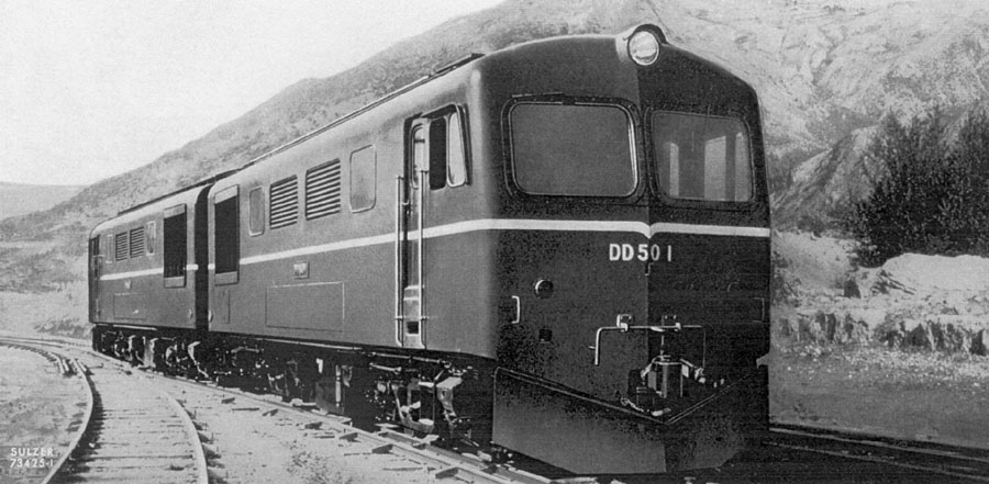
| Japan National Railways | 8LDA25 1,000hp | Mitsubishi Heavy Industries 1953-1955, Bo-Bo, 3ft 6in | Mitsubishi Electric | 6 | DD501 - DD506(1) |
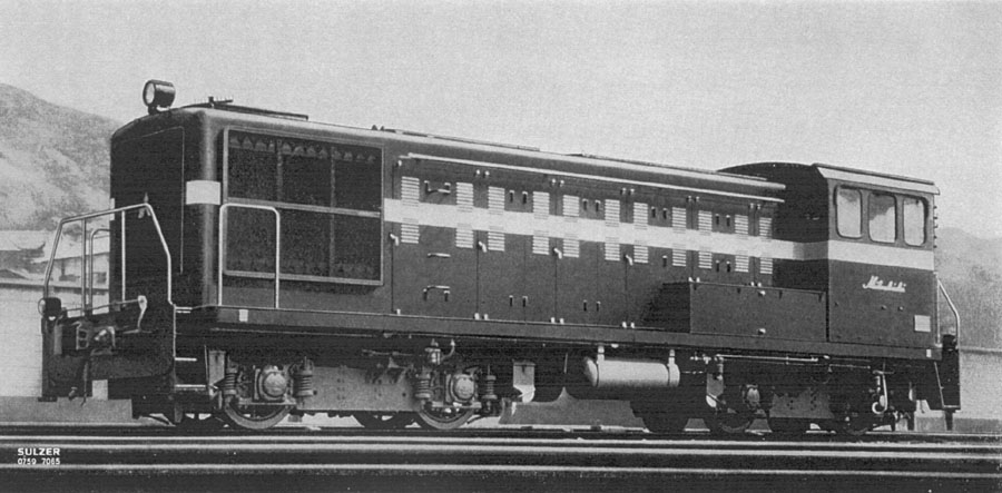
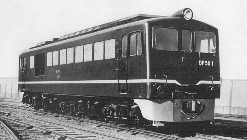
| Japan National Railways | 6LDA22 750hp | Mitsubishi Heavy Industries 1954, Bo-Bo, 3ft 6in | hydraulic | 1 | # ?? | Japan National Railways | 8LDA25 1,200hp | Mitsubishi Heavy Industries 1957-62, Bo-Bo-Bo, 3ft 6in | Mitsubishi Electric | 65 | DF50 01 - DF50 65(2) |
Notes
(1) Single ended BoBo, diesel electric - 900hp at 800rpm/1,000hp at 850rpm, length 11,900mm, weight 57.9/61.1 tons (empty/operating), speed 90km/h, gear ratio 73:16.
(2) 'D'= diesel; 'F'= six driving axles; Double ended BoBoBo, 1,060hp at 800rpm/1,200 at 850rpm, length 16,400mm, weight 78.2/84.2 tons; '5'= max speed greater than 90km/hr, gear ratio 72:17.
Built for narrow gauge 3'6" lines.
All withdrawn by August 1983, three preserved: DF50 1, 4 & 18.
Sulzer engines built under license by Mitsubishi.
![]()
![]()
![]()
Japanese National Railways (JNR) certainly adopted a different approach to the development of its diesel fleet, working with the industry to develop standard designs that could be built by several manufacturers. This process had been followed since the later 1920s with electric locomotives, but it was probably a more difficult exercise in the diesel case.
Some of the early Japanese prototype diesels, such as the Hitachi DF90, were evidently company designs, built to meet perceived JNR requirements. The DD50, built in a small series, may also have been more Mitsubishi than JNR. The DF50 was evidently a co-operative design, probably with fairly major input from JNR. Mitsubishi may have provided the most significant industry input, with Hitachi contributing primarily in respect of the MAN-engined variant. But that is unknown, as is wherefrom came the idea for the single-frame tribo layout. That was hardly new; Alsthom had been the first to use it for a diesel-electric locomotive, and before that GE had used it for a DC electric locomotive, with several examples and variants of the type to be found worldwide, including one (by GE) with an unpowered centre bogie. But JNR was the first large-scale user, and effectively 'made it its own', subsequently using it widely for electric as well as diesel locomotives. One could say that JNR used Bo-Bo-Bo where many others would use Co-Co, and Bo-2-Bo where many others would use A1A-A1A. It is believed the DF50 was the only single-frame tribo to have asymmetrical bogie spacing.
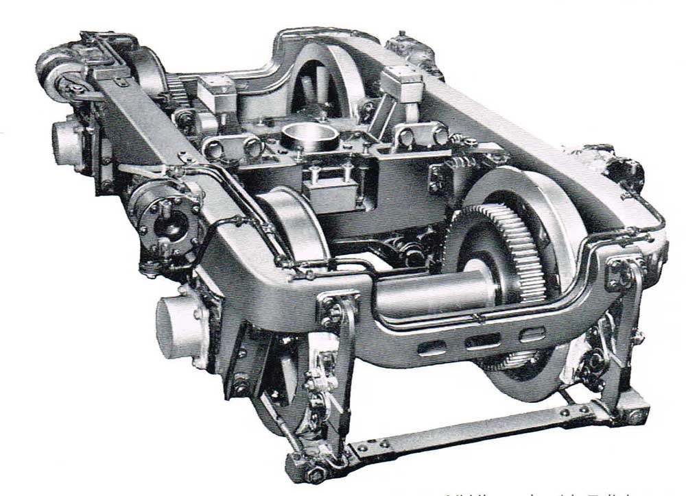
A 'T-link' was system used to allow significant free lateral motion for the DF50 centre bogie. The outer bogies were of the outside swing hanger type, with it is believed, the bolster arching up from under the bogie frame to load the coil secondary springs that loaded directly on the swing hangers, although there appears to have been a normal spring plank. At a later date JNR moved to roller platforms to provide centre bogie lateral movement in its tribo locomotives, at least those with powered centre bogies, and this was also found in export tribo models, such as the NZR Dj class and the ENFE Bolivia 900 class. The roller platform seems to be been originated by Baldwin-Westinghouse for the Pennsylvania E3b class AC electric locomotive prototypes.
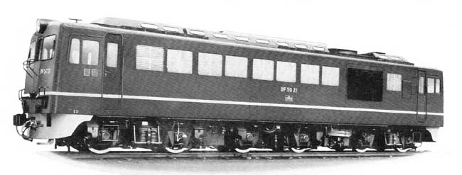
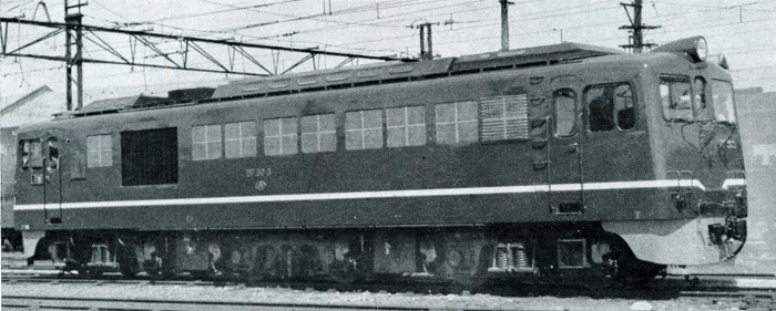
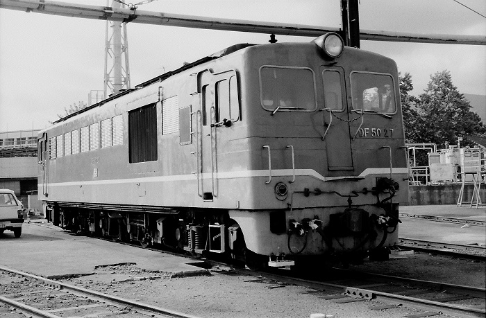
The DF 50 followed on from the DD 50, but was equipped with a three bogie B-B-B axle arrangement to allow use not only on the mainline but also on branch lines, in both passenger & freight service. For the former type of service a steam generator was fitted. The locomotives were powered by engines built by two manufacturers, the Sulzer powered machines were built by Mitsubishi, the MAN powered machines by Kawasaki & Hitachi. The engines were interchangeable although their rated horsepower were different, 1,200 hp for Sulzer & 1,400hp for MAN. In order to accommodate multiple unit working the locomotives were equipped with multiple control system and end doors to allow crew movement between locomotives.
The body was of the box type using pressed steel to reduce weight. Four openings in the roof allowed for removal of all the major compenents. The front and rear bogies were of the ordinairy 2-axle swing bolster type. The middle bogie was equipped with a T shaped link mechanism, the equivalent length of which is made infinite, allowing the bolster to move laterally from the body center to within 150mm on either side, permitting the locomotive to negotiate curves of 100m radius. All the trucks were equipped with coil spring of small spring constant to provide riding quality similar to that of a passenger car. The B-B-B axle arrangement gave less thrust to the rail, allowing for operation on lower standard track. The axle journals were of the cylindrical roller bearing type, with single-row angular contact type ball bearings and oil resisting rubber blocks to handle the bearing thrust at the axle ends. Each wheel was provided with a brake cylinder.
A Sulzer 8LDA25 engine had performed well in the DD 50 type, it would be applied to the DF 50, but uprated from 1,000hp to 1,200hp (8LDA25A) by altering the supercharging ratio through redesign of the piston and its cooling system. The main & auxiliary generators were arranged in tandem, with the auxiliary generator having an exciter for the main generator driven by V-belts. The larger electrical components were not interchangeable between the two engine types but many of the smaller electrical parts were. The six traction motors were electrically connected in such a way that that three sets of circuits, in which two traction motors were joined in series, were joined in parallel. The control equipment was located in a cabinet behind the No.1 end cab. The radiator fan, water pump, traction motor blowers, the steam generator and cab heaters were all powered by separate motors.
The Sulzer 8LDA25A engine was a water cooled, four cycle, vertical in line, direct injection with an exhaust gas supercharger. The cylinder bore was 250mm, the stroke 320mm, with a displacement of 126 litres, producing a continuous rating of 1,060hp at 800rpm and a one hour rating of 1,200hp at 850rpm. They were built by Mitsubishi Heavy Industries.
The main generator was separately excited, semi-closed, 9 poles with interpoles. The continuous rating was 700kw/225V/520amp/410rpm.
The six traction motors were closed, series winding, separately ventilated, 6 poles with interpoles. The continuous rating was 100kw/225V/520amp/410rpm. The traction motors were nose suspended with a gear ratio of 72:17.
The brake system was of the EL 14A type air brake & hand brake with C 3000 type motor driven air compressor.
The characteristics of the locomotive allowed haulage of a 500 ton train at 90 km/h on level track or a 300 ton train in excess of 17.5 km/h on hilly grades.
The selected statistics below are for the 1956 built DF50, those in red are for the earlier 1953 built DD50:
Gauge: 1,067mm
Axle arrangement: B-B-B; (DD50): B-B.
Length, width, height: 16,400mm, 2,932mm, 3987mm; (DD50): 11,900mm, 2,925mm, 4,014mm
Wheel base - total: 12,300mm; (DD50): 7,850mm.
Wheel base - truck: 2,300mm; (DD50): 2,300mm.
Distance between bogie centers: 4,700mm between No.1 & No.2 & 5,300mm between No.2 & No.3; (DD50): 5,550mm.
Driving wheel diameter, new/minimum: 1000mm / 920mm; (DD50): 1,000/920.
Weight in working order empty: 84.2 tons (winter), 78.2 tons (summer); (DD50): 61.1 tons(winter), 57.9 tons (summer).
Axle load in working order: 14 tons; (DD50): 15.3 tons.
Maximum operating speed: 90 km/h; (DD50): 90 km/h.
Continuous rating speed: 17.5 km/h; (DD50): 29 km/h.
Continuous rating tractive effort: 12.5 tons; (DD50): 6.5tons.
Fuel tank capacity: 1,500 litres (engine), 500 litres (steam generator); (DD50): 2,000 litres.
Water tank capacity: 3,000 litres (steam generator); (DD50): none.
Steam generator: SG 4 type, mono tube, forced circulating boiler-evaporating capacity 800 kg/hr, 8-12 kg cm2; (DD50): none.
Manufacturers of the mechanical parts for the DF50 were Hitachi, Kawaski Rolling Stock, Kisha Seizo, Mitsubishi Heavy-Industries, Nippon Sharyo & Tokyo Shibaura Electric.
DF50 1 - DF50 65 built by Mitsubishi except DF50 21 & DF50 40 by Kisha Seizo and DF50 22 by Hitachi, all were delivered between February 1957 & October 1962.
DF50 1 - DF50 7 were considered prototypes with slightly different sized front windows, different cab roof profiles, intermediate bogie center position, equipment arrangement, etc. being slightly different from the following production locomotives.
Manufacturers of the electrical parts for the DF50 were Fuji Electric, Hitachi, Kawasaki Heavy-Industries, Mitsubishi Electric, Tokyo Shibaura Electric & Tokyo Electric.
From the above statistics an interesting feature of this B-B-B or 'tribo' design is the asymmetric disposition of the middle bogie; it is displaced 300 mm towards the 'A' (?) end. This is most unlikely unusual; other tribo locomotives have the middle bogie positioned dead centre.
Notwithstanding that there were both MAN and Sulzer engined variants of the DF50, the control system for both is definitely of Sulzer origin, possibly reflecting the fact that the latter had very definite views on the subject.
The MAN-engined DF50 was the progenitor of MAN-engined exports built by Hitachi (and some by Mitsubishi) for Thailand, Sudan, Bolivia, Congo and Nigeria. These form a diverse group, the tribo design for Bolivia apparently being closest to the Japan National Railways DF50.
Operations summary
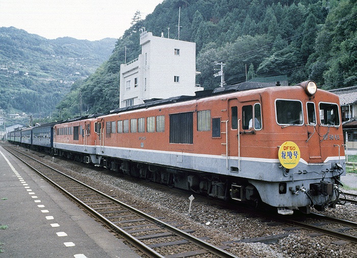
The DF50 locomotives entered service with issues but eventually found a home on passenger services on the main non-electrified trunk lines. They were considered insufficient in terms of performance to replace steam locomotive-hauled freight trains. In 1962 the DD51 Class entered service, eventually totalling 649 locomotives, these new powerful twin-engined locomotives and the continuing progress of electrification saw the DF50 Class concentrated in the Kameyama Engine District, Yonago Engine District, Takamatsu Driving Station, Kochi Engine District, Miyazaki Engine District, Sanin Main Line, Kise Main Line. They would also see some use on the Yosan, Dosan and Nippō Main Lines.
The Yonago DF50s combined the Sulzer & MAN powered types for use on all lines of the San-in Main Line and the Fukuchiyama Line, however by October 1978 they were replaced by the DD51 Class.
The Kameyama DF50s were used on the Kise Main Line, Kansai Main Line East, and Hanwa Line, but with the Shingu electrification in October 1978, they were put into operation east of Kii-Katsuura. This included haulage of the 'Kii' sleeper express, but in June 1979 a gradual changeover took place to the DD51 Class. The use of the DF50s in this area ended in March 1980.
The Miyazaki DF50s combined the Sulzer & MAN powered types on a variety of trains including the Nippō Main Line. Advancing electrification reduced the usage of the DF50s, but continued to be used on the sleeper expresses, including the 'Fuji' and 'Comet' until the entire line was electrified.
In Shikoku the Sulzer & MAN powered DF50s until October 1981 when the regular passenger services saw the MAN powered DF50s replaced by the DE10 Class. The Sulzer DF50s remained on the freight trains until September 1983 when the DE10 Class took over. On September 25th the temporary express train 'Sayonara DF50 Tosaji-go was operated by DF50 1 & DF50 65 to mark the end of the Class. Reportedly DF50 34 hauled the last freight train.
Casualties
Six DF50s were retired prematurely, presumably from collision/fire damage:
DF50 No.10: derailed & burned due to a landslide on June 25th 1964, Kise Main Line Taki to Kuki train 135 between Ozoneura & Kuki.
DF50 No.29: retired 1977.
DF50 No.35: retired December 26th 1977, after an unknown accident.
DF50 No.39: derailed and overturned into paddy field near Kii-Hioki station on January 24th 1969, Kise Main Line Nagoya to Tennoji train 921.
DF50 No.45: derailed due to a landslide and fell into the Anauchi River on July 5th 1972, at Shigefuji Station on the Dosan Main Line; locomotive scrapped in-situ, part of the car body remain buried in the river.
DF50 No.569: whilst working a local train from Takamatsu to Matsuyamaa 569 collided with a road crane on March 22nd 1978, on the Yosan Main Line between Takase and Hiji O damaged one side of the locomotive, retired due to impending withdrawal of this Class.
Operations & Casualties information translated from Japanese language Wikipedia article about the JNR DF50 locomotives.
![]()
Japanese National Railways (JNR) DF50 Class
By Steve Palmano
This article primarily focuses on the MAN powered JNR DF50 Class (Nos.501-573) but intertwined with the earlier Sulzer powered DF50 Class (Nos.1-65).
The Cape gauge DF50 was JNR’s first series-built line-service diesel locomotive. It was evidently the result of a joint design effort between JNR and the Japanese locomotive building industry, including but not limited to Hitachi, Kawasaki and Mitsubishi, with JNR defining the basic requirements.
Prior to that, JNR had acquired six of its DD50 class in 1953-54. These, built by Mitsubishi, were single-ended boxcab Bo-Bo units that could be worked back-to-back in MU pairs. Mitsubishi being a Sulzer licencee, they were fitted with Mitsubishi-Sulzer 8LDA25 engines, set to produce 900 bhp at 800 rev/min on a continuous basis, and 1000 bhp at 950 rev/min on a one hour basis. Weight was 61 tonnes, and maximum speed was 90 km/h.
As well, some builders submitted prototypes for evaluation by JNR, including Hitachi with the DF90, as discussed in an earlier chapter. Another was the Kawasaki DF40 of late 1955. This was a 75 tonne double-ended Co-Co unit powered by a Kawasaki-MAN V6V22/30AmA engine set to provide 1200 bhp on a continuous basis.
In JNR’s view, none of the above met its requirements. These developed to be for a locomotive that could be used on branch lines laid with 30 kg/m rails as well as on trunk lines, with an axle loading of not more than 14 tonnes, and with minimal side-thrust on tight curves. On-board passenger train steam heating was a requirement.
Possibly the DF40 came close in some respects, but Co-Co running gear would not meet JNR’s low side-thrust requirement on branchline curves, and it did not have train heating equipment. On the other hand, six axles were necessary in order to meet the axle loading requirements, particularly with the additional weight of steam heating equipment. It is understood that Mitsubishi suggested the single-frame tribo Bo-Bo-Bo layout as solving the side-thrust problem, although I have not seen “hard” confirmation of that. The single-frame tribo layout was not new, but had seen little prior use. JNR’s decision to use it for a quantity-produced type was thus a major turning point.
Perhaps the DF50 could be seen as being a stretched DD50 with three rather than two bogies. The “stretch” then would have been what was needed to accommodate a second cab and a train heating boiler, and perhaps more still to allow room for the three bogies with adequate interbogie space for underhung equipment. Alternatively, and notionally at least, it could be seen as a stretched DF40, with the addition of train heating equipment and three two-axle in place of two three-axle bogies.
With electric locomotives, JNR practice for major classes had been to share the work around the industry, with all participants building to a common design. In the diesel-electric case, where the different builders had different engine design licensing arrangements, that was not possible. To accommodate that situation, JNR arranged for there to be two versions of the DF50, one with the Mitsubishi-Sulzer 8LDA25 engine, and the other with the Hitachi-MAN and Kawasaki-MAN V12V22/30AmA engine. The former seems to have been viewed as the baseline version, with the latter as a variant. That suggests that the design may have been more of a DD50 than a DF40 derivative.
The Sulzer-engined variant had a Mitsubishi-design main and auxiliary generator assembly, whilst the MAN-engined variant had a Hitachi main and auxiliary generator assembly, which was somewhat different. Beyond that, the locomotives were essentially the same, and both versions used the same JNR standard traction motor type.
Whether the two engine-generator assembly types could be interchanged in a given frame is unknown. Whilst it would have been possible to allow for this, it may have added unjustifiable complication as compared with tailoring the frame details to accommodate just one type of assembly.
The result was a double-ended boxcab locomotive of 15.6 metres length over end frames, that is fractionally longer than the DF90. Unusually for a tribo locomotive, the bogie centres were asymmetric, at 4.7 metres between bogies #1 and #2, and 5.3 metres between bogies #2 and #3. Presumably this was done to obtain the correct weight distribution. According to JNR data , the total weight was 84.2 tonnes, with the axle loading approximately 14 tonnes. Hitachi data though shows the weight as 81 tonnes, with a 13.5 tonne axle loading. One would expect at least a small weight difference between the two variants. Possibly the Hitachi-MAN version was ballasted to match the Mitsubishi-Sulzer version, but that is speculation my part.
The three bogies, of the pedestal type, all had cast frames. Primary suspension was by long-travel coil springs in the pedestals and above the axleboxes, there being no equalization. The outer pair were essentially of the conventional swing-bolster type. They did though have long outside swing links, with coil bolster springs, this being a change from the DD50, which had inside swing links.
The central bogie had a different arrangement to allow it significant and relatively free lateral motion. Instead of a conventional swing links, it had a mechanism with T-shaped links that had an infinite equivalent length. This allowed the bolster to move 150 mm either way from the centre position, in turn allowing the locomotive to negotiate curves down to 100 metres radius, with some reserve. I have never found a diagram of this T-link system, nor does the available image of the centre bogie reveal its nature. It would appear though that the centre bogie did not have any secondary springing. And presumably, the T-link mechanism was non-lifting. The outer bogie swing motion would not have been non-lifting, but the long swing links probably reduced its magnitude to the point where interbogie weight transfer was minimal.
As said, the Mitsubishi version of the DF50 had the Mitsubishi-Sulzer 8LDA25A engine, set to provide a continuous output of 1060 bhp at 800 rev/min, and a one-hour output of 1200 bhp at 850 rev/min. The Hitachi/Kawasaki version had the Hitachi-MAN (or Kawasaki-MAN) V6V22/30mA engine set to provide 1200 bhp (JNR number, Hitachi claimed 1260 bhp) at 900 rev/min on a continuous basis, and 1400 bhp at 1000 rev/min on a one-hour basis.
The Mitsubishi version had a Mitsubishi generator assembly comprising a main generator with an overhung auxiliary generator, plus an exciter mounted atop the latter and belt-driven from it. The Hitachi/Kawasaki version had a Hitachi design generator assembly. With this, as was the case for the DF90, the auxiliary generator was driven by speed-increasing gears by a separate shaft inside the main generator shaft. The exciter was mounted upon and belt-driven from it. The latter was a change from Hitachi’s established practice of gear-driving both the auxiliary generator and exciter. Possibly it was done to align with the Mitsubishi arrangement. Probably for the same reason, the exciter was mounted above rather than alongside the auxiliary generator.
The control system followed Mitsubishi practice, which in turn followed Sulzer practice. The latter was explicitly based upon the Lemp 1914 patent. (Sulzer was always careful to acknowledge Lemp’s early work, something that was seldom done by other manufacturers.) The evidence indicates that the DF50 had a similar control protocol to the DD50, and that the two types could work together in MU. The 8LDA28A engine had a Sulzer governor, with internal pneumatic speed control and an internal load control pilot valve controlling an external load regulator rheostat. The control scheme had five stepwise fixed excitation starting notches at minimum engine speed. Notches 6 through 19 were of the load control type at successively increasing engine speeds from minimum at notch 6 to the continuous rating speed at notch 18, and the one-hour rating speed at notch 19. For these, engine speed was controlled pneumatically from the throttle handle with stepwise increasing air pressure. (Quite possibly, the DD50 was the first application of this system, which superseded Sulzer’s previous (1939) system with stepped electric control of engine speed, typically with 10 notches total of which eight were of the load control type.)
The same system was applied to the MAN V6V22/30mA engine, in this case with what was described as an independent governor. This may well have been the Woodward PG type with pneumatic-hydraulic speed control calibrated to match the Sulzer protocol. It may be noted that pneumatic speed control of the MAN 22/30 engine was not new, having already been used for some diesel-hydraulic locomotive applications. In this case, Hitachi was obliged to depart from its established nine-notch electric control system.
The DF50 was equipped for MU. Presumably, it could also work in MU with the DD50. And the solitary DF40 prototype was later modified to have a DF50-type control system so that it could work with the latter class. (Details of its original control system are unknown.)
The traction motors were of the JNR MT48 type. Historically, JNR had long standardized traction motors for its electric locomotives, with all participating builders producing interchangeable versions. The same practice was evidently continued for its first series-production diesel-electric design. The origins of the MT48 are unknown. JNR data record it has having been a six-pole machine. Hitachi had used a four-pole motor for the DF90, as had Mitsubishi for the DD50. So, the MT48 might have been originated by another maker.
The DF50 motors were connected in permanent 2S3P. They had two stages of field weakening, to 50% and 30% of full field, the same points as had been used by Hitachi for the DF90. (The corresponding data for the DD50 are unknown.) They drove 1000 mm diameter wheels via 72:17 gearing. Maximum speed was 90 km/h.
Maximum tractive effort was given as 21 000 kgf, at 25% adhesion, for both versions. So, this was an adhesion limited number. Continuous tractive effort for both versions was 12 5 00 kgf, at 17.5 km/h for the Mitsubishi version and at 19.3 km/h for the Hitachi/Kawasaki version, the higher minimum continuous speed of the latter simply reflecting its higher power output. Notch 17 on the MAN version equated to notch 19 on the Sulzer version. At the lower end, the MAN notches were probably similar to the Sulzer notches, but developed bigger spacings further up the power range. Weak field was not available until notch 11.
The DF50 had electrically-driven auxiliaries, using the standard Japanese “100-volt” system. The auxiliary generator capacity was 40 kW continuous, 45 kW short-term.
The air braking system was of the EL14A-R type, a variant of the Japanese EL14 group.
The total DF50 class build was 138 over the period 1957 to 1963. Of these, 65 were the apparent baseline model with the Sulzer 8LDA25A engine. These were built variously by Mitsubishi, Kisha Seizo Keisha (KSK) and Nippon Sharyo over the 1957-1962 period, although the numbers for each builder are unknown. 73 were the alternative model with the MAN engine, known as the DF50 500 class. These were built by Hitachi (34), Kawasaki (37) and Toshiba (2: 509 & 538). The build period is sometimes quoted as 1958 to 1963, but the first may actually have been finished late in 1957.
The 73 MAN powered locomotives DF50 501 to DF50 573 were delivered April 1958 to October 1963.
The DF50 lasted in service until 1983, although the DF50 500 is reported as having made its exit in 1981. Whether that was because of its relative performance is unknown. It is reasonable to assume that the two variants were assigned to different sections of the system, and that the DF50 500 departed first may simply have been the result of the way the fleet was run out, area-by-area. When it was designed, the DF50 had about as much power as could be accommodated on a single-powerplant diesel-electric locomotive with a 14 tonne axle loading, and which was restricted to having three short wheelbase two-axle bogies. It turned out that more power was desirable, and thus JNR worked with Hitachi to develop the 2000 bhp DD51 B-2-B diesel-hydraulic locomotive as standard model for mass production, the prototype appearing in 1962. As a centre-cab unit with relatively low hoods, it also had broader utility.
The JNR DF50 was the first single-frame tribo design built in quantity. More than that, it was JNR’s start on the tribo vector, which became that operator’s standard locomotive form where six axles were required, whether all powered or not. In the 1960 to 1962 period, a raft of JNR tribo designs appeared, covering AC, DC and dual-system electric locomotives and diesel-hydraulic locomotives, with wheel arrangements variously Bo-Bo-Bo, B-B-B, Bo-2-Bo, B-2-B and B-1-B.
The use of two quite different powerplants, from different builders, in the same basic design was an unusual, although not unique feature of the DF50. Inter alia, SNCF, France did that with some of its diesel-electric designs, as did DB, Germany in the diesel-hydraulic field, and Alsthom with some of its export diesel-electric models. The DF50 though, appears to have been the only case where MAN and Sulzer powerplants were used alternatively in the same design.
With the DF50, Hitachi did depart somewhat from the precepts that it had established with the DF90, particularly in respect of the control system, and to some extent with the generator assembly. Anyway, the multipartite nature of the DF50 did make it something of an outlier in the locomotive sequence at interest.
Sources: Article dated July 1957: Diesel Locomotives & Diesel Railcars in JNR by Atsuo Kinugasa.
Wikipedia: JNR DF50 Class locomotives
Steve Palmano contributor for both primary articles.
Page added April 30th 2005.
Page update January 5th 2025.
Return to Sulzer page
Return to site menu